Description
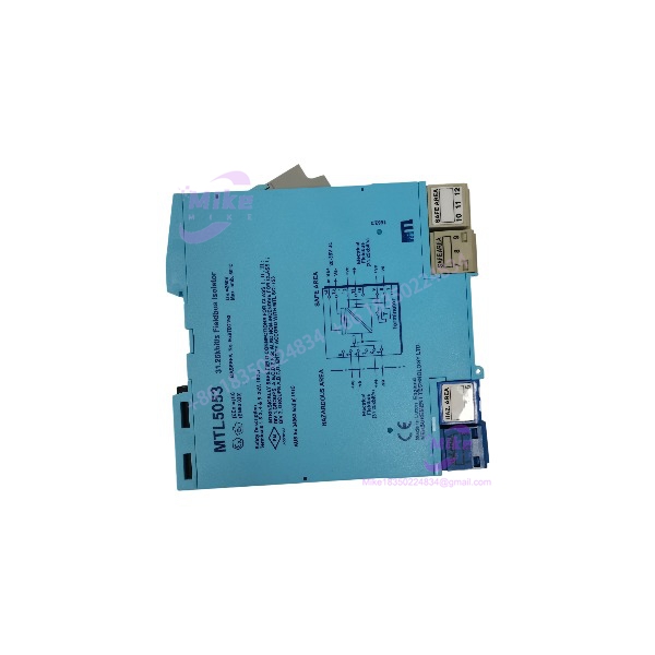
Eaton MTL5053 | Fieldbus Isolator and Power Supply Module
Architect’s Product Breakdown
The Eaton MTL5053 operates as a specialized fieldbus isolator and power supply engineered to bridge safe-area control systems with 31.25 kbit/s H1 fieldbus devices located in explosive hazardous environments. Within a distributed control architecture, the MTL5053 delivers galvanic isolation between circuits while supplying regulated power and passing bidirectional digital communications to hazardous-area instruments.
Integrating this unit into control cabinets requires strict adherence to thermal management and mounting guidelines. Because the MTL5053 handles continuous power conversion loads, spacing requirements and orientation on the DIN rail dictate safe thermal dissipation limits. Neglecting proper enclosure ventilation or mounting spacing under heavy operational loads will trigger thermal derating and shorten component lifespans.
MTL5053
Key Technical Specifications
| Parameter | Specification |
| Model Designation | MTL5053 |
| Supply Voltage | 20 to 35 V DC |
| Hazardous-Area Output | 18.4 V ±2% at up to 80 mA max current |
| Digital Transmission | Compatible with 31.25 kbit/s fieldbus systems (H1) |
| Current Consumption | 135 mA typical at 24 V DC (with 80mA load) |
| Power Dissipation | 2.3 W typical at 24 V DC |
| Galvanic Isolation | 250 V AC peak between safe and hazardous circuits |
| Internal Terminator | Switch-selectable for short safe-area bus lengths |
| Ambient Operating Temperature | -20°C to +60°C (optimized horizontal mount) |
| Mounting Style | 35 mm DIN Rail |
Field Engineer’s Pitfall Guide
- WARNING: Thermal Orientation Limits. Mounting the MTL5053 in a non-optimum vertical plane without adequate airflow will force a reduction in the maximum operating temperature threshold down to 45°C. I once watched a plant commissioning team lose an entire fieldbus segment during an afternoon heat run because dense module packing trapped heat directly around the housing.
- WARNING: Unused Shield Terminals. Do not mistake screw terminals 3, 6, 7, and 10 for internal earth grounds; they are strictly provided to assist with physical cable screen termination and lack internal chassis connections.
- WARNING: Power Supply Voltage Sag. Ensure the 24V DC bulk power supply does not experience voltage sags below 20V DC under transient plant loads, which will cause the unit to drop out and interrupt H1 communication loops.
QA & Testing SOP
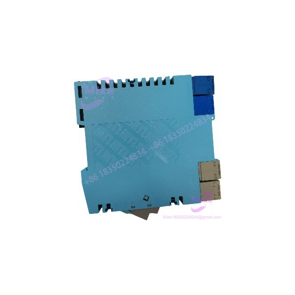
- Visual & Origin Verification: Inspect the molded polyamide enclosure for cracks, verify OEM nameplate laser markings, and ensure front LED indicators and terminal blocks are undamaged.
- Power-Rail Bench Test: Mount the on an isolated DIN rail test rig, apply a regulated 24V DC input, and verify steady green power LED illumination.
- Output Voltage & Load Check: Measure the hazardous-side output terminals to confirm the 18.4V DC nominal output is stable under an active simulated load test.
- Isolation Verification: Execute an insulation resistance test to validate the 250V AC galvanic isolation barrier between safe-area and hazardous-area circuits.
- Packaging: Seal in an anti-static moisture-barrier bag and pack with dense foam padding inside an exterior box.
Technical FAQ
Can the be installed directly inside a hazardous area zone?
No. The module itself must be installed in a safe area or an approved purged/certified enclosure, but its output connects safely to devices located in Zone 0, 1, or 2.
When should I enable the internal bus terminator switch?
The switch on top of the module should be enabled only when the safe-area bus length is short and requires an internal termination impedance.
What causes the green power LED to remain unlit during operation?
An unlit LED typically points to a blown input fuse, incorrect supply polarity, or a bulk DC power supply voltage dropping below the 20V DC minimum threshold.
Is it necessary to use module spacers between units on the DIN rail?
Yes. To ensure adequate heat dissipation under maximum load conditions, maintaining a 10mm space between adjacent units using recommended spacers is advised.