Description
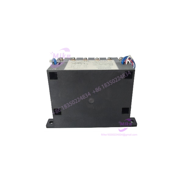
Yaskawa HV-75AP4 | 75A Spindle Winding Contactor
Dynamic Product Introduction
A spindle system with multiple motor windings has a very different switching requirement from an ordinary three-phase motor starter. The contactor has to change the motor’s winding configuration as part of the drive’s speed/torque operating strategy. That is exactly where the HV-75AP4 belongs.
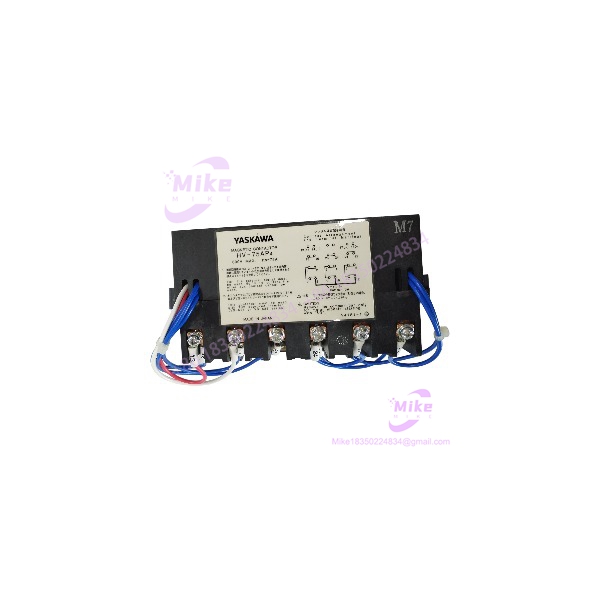
Yaskawa identifies the HV-75AP4 specifically as a magnetic contactor for winding selection. The standard version uses three normally open and three normally closed main contacts, plus an auxiliary contact, allowing the winding-selection circuit to change between defined states under the control of the spindle system.
This model appears in Yaskawa documentation for equipment including the Varispeed 626M5 family and later Sigma servo/spindle documentation. The associated HV-150AP4 and HV-200AP4 models provide higher current capacities, so the 75 A designation is a meaningful part of the selection rather than merely a catalog size.
For procurement, the important distinction is simple: HV-75AP4 is a winding-selection contactor, not the drive itself. Replacing it with a generic 75 A contactor without matching the normally-open/normally-closed contact arrangement, coil voltage, auxiliary contacts, mechanical mounting, and spindle control sequence can produce a machine that powers up but cannot correctly execute its winding-selection logic.
HV-75AP4
Key Technical Specifications
- Model: HV-75AP4
- Manufacturer: Yaskawa
- Component type: Magnetic contactor for winding selection
- Main contact arrangement: 3NO + 3NC
- Auxiliary contact: 1NC in current Yaskawa documentation
- Rated insulation voltage: 600 V
- Continuous applying current: 75 A
- 30-minute applying current: 87 A
- Breaking current capacity at 220 V: 200 A
- Breaking current capacity at 440 V: 150 A
- Open/close frequency: 600 operations/hour
- Mechanical duration of life: 5,000,000 operations
- Control magnetic coil: 200 V 50/60 Hz; 220 V 50/60 Hz; 230 V 60 Hz
- Ambient temperature: -10 to +55°C
- Storage temperature: -20 to +85°C
- Humidity: 10–95% RH, non-condensing
- Spindle motor capacity: 5.5–15 kW at 50% ED
- Mass: 2.5 kg
- Mounting: Four M6 mounting holes
- Main terminals: M5
- Control terminals: M4
- Approximate overall envelope: 160 × 110 × 92 mm, with the manufacturer’s dimensional drawing showing additional mounting/terminal offsets
These specifications come directly from Yaskawa’s published peripheral-device documentation.
Application and System Compatibility
The HV-75AP4 is intended for applications where a Yaskawa drive controls a spindle motor with selectable windings.
Yaskawa’s documentation associates the component with spindle-drive equipment and gives a 5.5–15 kW spindle motor capacity at 50% ED. Earlier Varispeed documentation also lists the HV-75AP4 against 200 V- and 400 V-class inverter applications, covering approximately 3.7–15 kW depending on the specific drive configuration.
Before replacing an existing contactor, verify:
- Exact HV-75AP4 model
- Standard versus HV-75AP4/UL
- Presence or absence of safety cover
- Coil voltage
- Main-contact arrangement
- Auxiliary contact arrangement
- Spindle motor winding configuration
- Drive model
- Machine wiring diagram
- Mounting-hole pattern
- Existing control-circuit terminal wiring
Yaskawa also documents HV-75AP4/UL as the UL-compliance version, so the suffix should not be ignored during international procurement.
Global Sourcing & Live-Test SOP
1. Inbound Verification
For a used or surplus HV-75AP4, inspect the physical unit before energizing it.
Record:
- Yaskawa model marking
- Serial number
- Date code if present
- Standard or UL designation
- Coil-voltage marking
- Contact configuration
- Terminal labels
- Condition of the four mounting points
- Condition of M5 main terminals
- Condition of M4 control terminals
Check the contact housing for cracking, carbonization, discoloration, or evidence of excessive switching current.
2. Coil Verification
The control coil is not a low-voltage PLC relay coil.
Yaskawa specifies:
- 200 V AC, 50/60 Hz
- 220 V AC, 50/60 Hz
- 230 V AC, 60 Hz
Verify the actual coil marking before applying control voltage.
A common field mistake is to assume that the machine’s control voltage is suitable simply because another contactor in the cabinet uses 24 VDC. The HV-75AP4 coil specification needs to be checked independently.
3. Contact Inspection
With the unit isolated:
- Check main-contact continuity.
- Verify the expected NO/NC states.
- Check auxiliary-contact operation.
- Measure contact resistance where appropriate.
- Inspect for welded contacts.
- Check mechanical movement.
- Listen for sluggish or abnormal armature movement.
A contactor can pass a simple coil test while still having degraded power contacts.
4. Live Functional Test
Use the correctly rated coil supply and suitable protection.
Verify:
- Pickup voltage
- Positive armature engagement
- Contact-state transition
- Dropout behavior
- Auxiliary-contact transition
- Excessive contact bounce
- Coil heating
Do not repeatedly cycle the unit at maximum frequency simply to demonstrate operation. Yaskawa specifies 600 operations/hour as the open/close frequency, while mechanical life is specified at 5 million operations.
5. Final Preparation
For a tested spare:
- Photograph the nameplate.
- Record coil voltage.
- Record measured contact resistance.
- Document NO/NC contact states.
- Record test-cycle results.
- Protect terminals against impact and contamination.
- Package the contactor so the armature cannot be mechanically damaged in transit.
Field Engineer’s Pitfall Guide
❗ 1. Do Not Treat HV-75AP4 as a Generic 75 A Contactor
The current rating is only one part of the specification. The HV-75AP4 has a defined 3NO + 3NC main-contact arrangement and an auxiliary contact, specifically for winding-selection service.
A conventional 3-pole 75 A contactor may have completely different contact logic.
❗ 2. Verify the Coil Before Applying Power
The documented coil is 200/220 VAC or 230 VAC, depending on the applicable frequency. It is not a standard 24 VDC PLC-output contactor.
Applying the wrong control voltage can destroy the coil before the spindle system ever gets a chance to operate.
❗ 3. Do Not Confuse HV-75AP4 With HV-75BP4
Yaskawa documentation distinguishes the AP4 and BP4 families in connection with different motor/inverter applications. Earlier documentation identifies HV-75BP4 as the IPM-motor counterpart.
When replacing a machine component, use the complete model designation from the original hardware and electrical drawings.
Intent-Driven FAQ
What is the Yaskawa HV-75AP4?
The HV-75AP4 is a magnetic contactor for spindle-motor winding selection. It is used as a peripheral component in Yaskawa spindle-drive systems rather than functioning as the drive itself.
What is the current rating of HV-75AP4?
Yaskawa specifies 75 A continuous and 87 A for 30 minutes. The rated insulation voltage is 600 V.
What motor size is the HV-75AP4 intended for?
Yaskawa specifies 5.5 to 15 kW spindle motor capacity at 50% ED for the HV-75AP4.
What coil voltage does the HV-75AP4 use?
The documented coil ratings are 200 V AC at 50/60 Hz, 220 V AC at 50/60 Hz, or 230 V AC at 60 Hz. Confirm the marking on the physical unit before installation.
What is the contact arrangement?
Yaskawa specifies 3 normally open and 3 normally closed main contacts, plus an auxiliary contact. Current Sigma documentation identifies the auxiliary contact as 1NC.
How long should an HV-75AP4 last?
Yaskawa specifies a mechanical life of 5 million operations. That is a mechanical-life specification, not a guarantee of electrical contact life under every spindle load. Actual electrical life depends on switching conditions and the connected circuit.
What should I verify before buying a used HV-75AP4?
At minimum, verify the exact model, coil voltage, main-contact configuration, auxiliary-contact configuration, standard versus UL version, physical mounting condition, and evidence of contact wear.
For a CNC spindle application, also confirm that the contactor is being used with the correct Yaskawa drive and winding-selection circuit. A visually identical contactor is not enough evidence of interchangeability.