Description
NI PXI-7344 | 62.5 µs Dual-Loop DSP Motion Controller Card
Dynamic Product Introduction
Upgrading or maintaining complex automated assembly lines often comes down to motion controller reliability and real-time synchronization. When multi-axis gantries or precision positioning stages experience trajectory lag, replacing the core motion hardware without rewriting legacy control routines becomes a top priority for plant engineers.
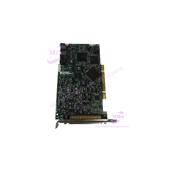
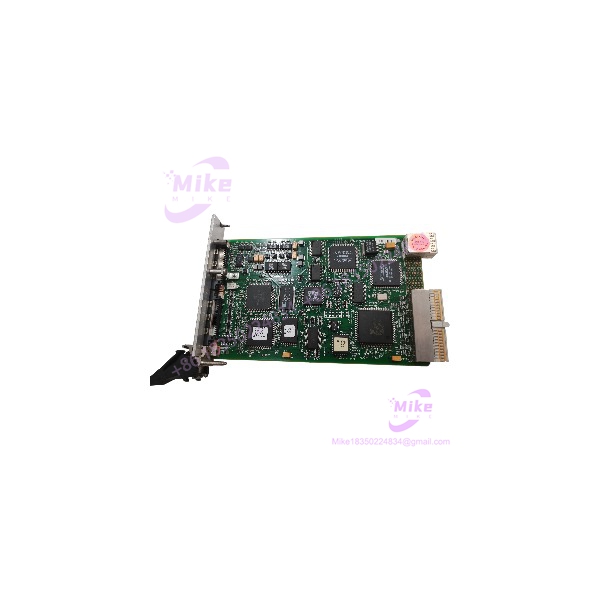
The NI PXI-7344 utilizes an integrated dual-processor architecture—combining a dedicated 32-bit CPU with a high-speed DSP—to handle complex trajectory profiling, velocity feedforward routines, and electronic gearing entirely on the card. Capable of driving any combination of 4 stepper or servo axes independently, the PXI-7344 provides hardware-timed position breakpoints and high-speed capture inputs. This dedicated processing capacity makes the PXI-7344 an essential component for semiconductor wafer handling, automated inspection rigs, and robotics integration.
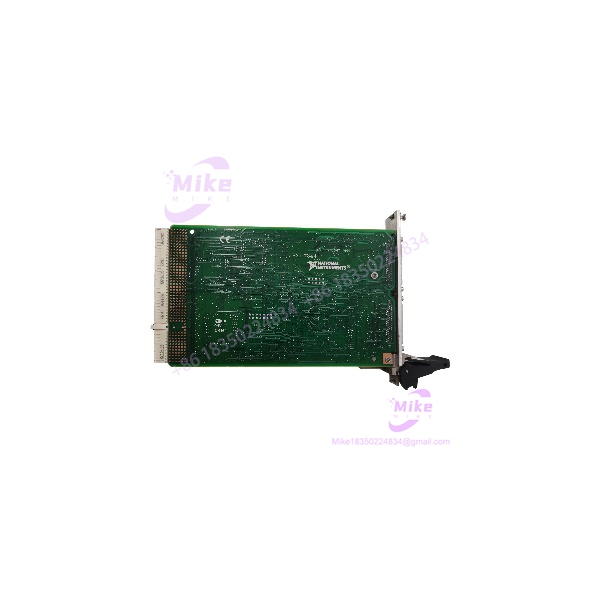
PXI-7344
Key Technical Specifications
- Number of Axes: 4 axes (independently software-configurable for stepper or servo operation)
- Processor Architecture: 32-bit main processor + dedicated trajectory DSP
- Servo Loop Update Rate: 62.5 µs per axis
- Trajectory Modes: S-curve, trapezoidal, velocity, point-to-point, circular/linear interpolation, and vector space control
- Encoder Feedback Types: Quadrature encoder (up to 20 MHz) and dual-loop feedback processing
- Analog Inputs: 8 ADC channels (12-bit, ±10 V range)
- Analog Outputs: 4 DAC channels (±10 V servo command output)
- Digital I/O Lines: 32 TTL lines (4 8-bit ports)
- Dedicated Motion I/O: Forward/Reverse limit inputs, Home switch inputs, Breakpoint outputs, High-speed capture inputs
- Bus Interface: Standard 32-bit PXI / CompactPCI slot interface
- Connector Type: 68-pin female VHDCI connector
Global Sourcing & Live-Test SOP (Transparency Core)
Sourcing legacy PXI hardware requires rigorous live testing to ensure field-readiness for high-precision manufacturing.
Inbound Verification & Traceability
- Paperwork Audit: Validation of physical serial numbers against factory manufacturing databases to verify hardware revision authenticity.
- Physical Inspection: Detailed inspection of the 68-pin VHDCI connector pins, backplane bus contacts, PCB trace integrity, and thermal condition of onboard drive components.
Live Rack Simulation & Diagnostics
- PXI Backplane Verification: Installed into an authentic PXI test chassis running PXI Trigger Bus lines to verify PCI system recognition and direct DMA memory mapping.
- Multi-Axis Loop Test: Connected via a Universal Motion Interface (UMI) to a 4-axis test bench equipped with optical encoders and servo/stepper drives.
- Trajectory & DSP Stressing: Executing continuous 3D circular interpolation and complex vector moves at maximum PID update rates (62.5 µs) to verify quadrature tracking and output linearity on a digital oscilloscope.
- 24-Hour Environmental Burn-In: Card undergoes continuous multi-axis profiling inside a temperature-controlled chamber to ensure thermal stability under maximum continuous DSP load.
Final Prep
- Firmware Checks: Verifying onboard EEPROM calibration and flashing current firmware revisions.
- ESD Safe Handling: Module is packaged in anti-static shielding materials with moisture absorbers and double-boxed for air transport.
The Field Engineer’s Pitfall Guide
- ❗ Amplifier Enable Line Polarity: When swapping out a PXI-7344, verify the default logic state of the drive inhibit/enable lines in Measurement & Automation Explorer (MAX). Incorrectly configured polarity will keep external servo drives disabled or trigger an instant axis fault on bootup.
- ❗ Encoder Line Noise & Ground Loops: High-speed 20 MHz encoder inputs are sensitive to shield grounding issues on long VHDCI cable runs. Ensure the motor drive frame ground is bonded to the PXI chassis ground to prevent encoder counts from drifting during high-acceleration moves.
- ❗ Unrouted Motion Trigger Lines: For systems utilizing hardware position breakpoints to trigger external camera vision acquisition, failing to map the RTSI or PXI Trigger Bus assignments in MAX will cause the system to miss image captures without generating a software error.
Intent-Driven FAQ
Will replacing a damaged PXI-7344 wipe my motion axis parameters?
No. Motion parameters—such as encoder counts per revolution, acceleration limits, and PID gain settings—are stored within your host application (LabVIEW, NI-Motion, C++) and MAX configuration files. Once the replacement PXI-7344 card is installed, the host software reloads these settings to the card upon initialization.
Can I control 4 servo motors and 4 stepper motors on one PXI-7344 card?
The card supports a maximum of 4 physical axes in total. However, those 4 axes can be configured in any combination—for instance, 3 servo axes and 1 stepper axis, or all 4 as servo axes.
Is the PXI-7344 hot-swappable in an active PXI chassis?
No. Standard PXI modules are not hot-swappable. Removing or inserting the PXI-7344 while the chassis backplane is powered can damage the bus interface and onboard DSP. Always shut off power to the chassis prior to card replacement.
What terminal block is recommended for wiring the PXI-7344?
The card connects via a 68-pin VHDCI port. NI recommends pairing the card with a shielded VHDCI cable and a UMI-7764 or UMI-7774 Universal Motion Interface breakout block for isolated signal wiring.
What warranty coverage comes with surplus or refurbished units?
Verified PXI-7344 modules include a standard 12-month full-replacement warranty covering hardware stability and component operational performance.
If you need help setting up breakout pinouts or verifying driver compatibility for your PXI-7344 installation, let me know your host OS and motor drive types and I can provide step-by-step guidance.