


Description
Honeywell CC-TDOB11 | 32-Channel Redundant Digital Output Termination Specs
Dynamic Product Introduction
Maintaining uninterrupted control over final elements during critical plant operations requires an output termination layer engineered explicitly for fault-tolerant architectures. When single-path digital output bases force critical control loops offline during routine card replacements, process stability takes an immediate hit.
Enter the Honeywell CC-TDOB11, a heavy-duty redundant Input/Output Termination Assembly designed to anchor high-availability 24 VDC digital control loops within Series C frameworks. By combining a dual-slot physical interface for 32 channels with built-in point-level electronic protection, this CC-TDOB11 hardware base eliminates single points of failure across crucial interlocks. Facilities upgrading to this redundant architecture experience superior system uptime and seamless live-replacement capabilities—though this strictly depends on precise carrier alignment and secure wire torque.
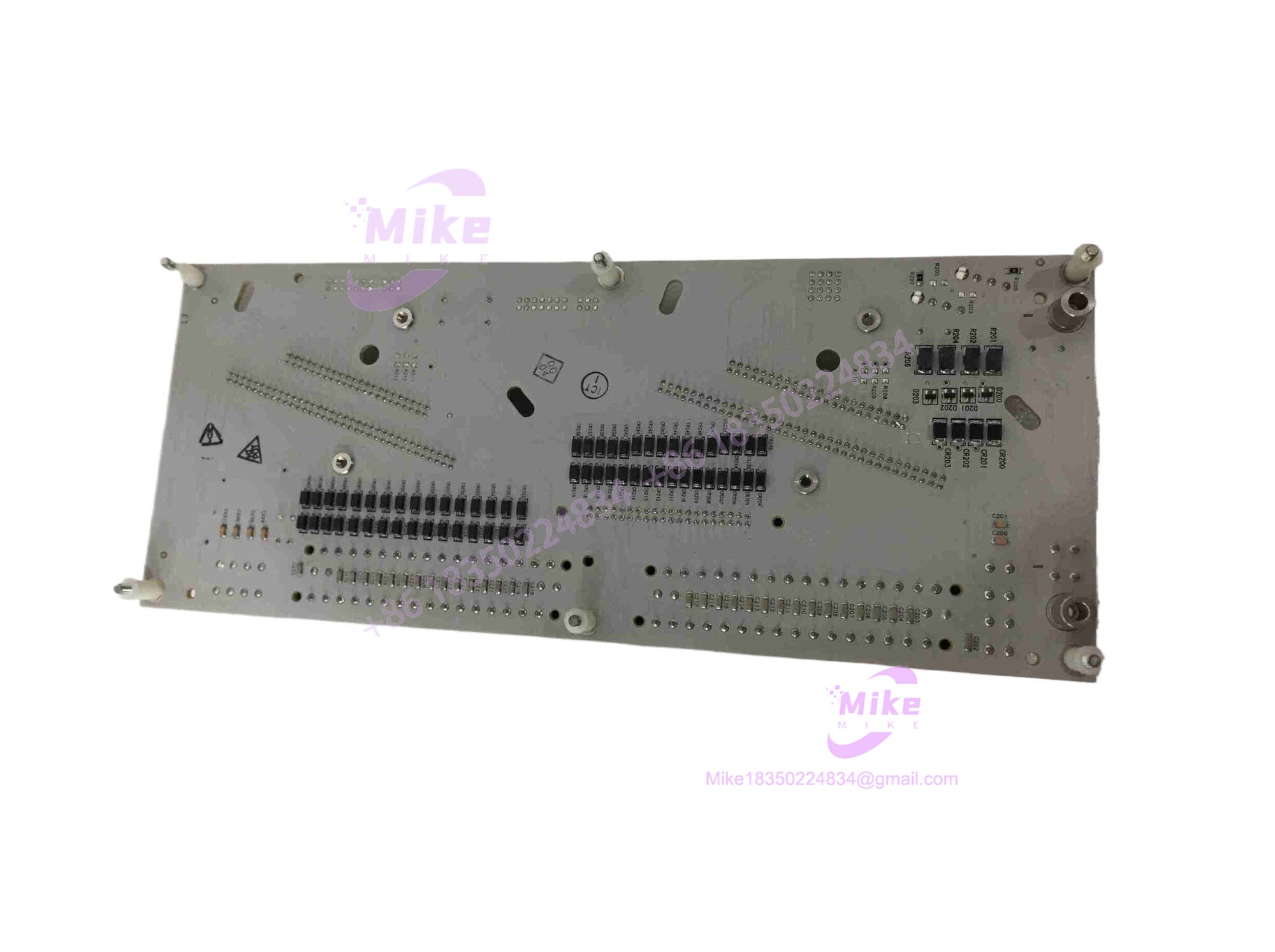
CC-TDOB11
Key Technical Specifications
| Core Parameter | Technical Specification |
| Module Series | Series C (Experion PKS) |
| Product Type | Redundant Digital Output IOTA Base |
| Channel Capacity | 32 Discrete Output Channels |
| Nominal Output Voltage | 24 VDC (Transistor Open-Collector) |
| Redundancy Support | Dual-Module Slot Architecture |
| Max Current per Channel | 500 mA (Continuous), 1 A (for 1 second) |
| Channel Protection | Electronic Over-Current Sensing & Point Shutdown |
| Operating Temperature | -40°C to +70°C |
| Mounting Architecture | Series C Chassis / DIN Rail Backplane |
| Approximate Weight | ~0.85 kg to 2.0 kg (Depending on Packaging) |
Global Sourcing & Live-Test SOP (Transparency Core)
Procuring surplus or replacement automation hardware demands an uncompromising quality control pipeline. In field deployments, dropping an untested board into a live rack can trigger catastrophic controller faults.
- Inbound Verification: Every incoming shipment of the CC-TDOB11 undergoes meticulous customs documentation review alongside high-magnification holographic serial number checks to block gray-market counterfeits.
- Live Simulation: Technicians mount the CC-TDOB11 hardware onto an authentic Series C test bench to verify dual backplane pin alignment and mechanical slot latching integrity.
- Diagnostics: Engineers execute full-scale load switching tests across dual output paths, verify point-level overcurrent trip thresholds using calibrated multimeters, and run a 24-hour thermal heat run to flush out infant mortality defects.
- Final Prep: Once cleared, the unit is logged by revision level, packed in anti-static shielding, and vacuum-sealed for storage.
The Field Engineer’s Pitfall Guide
❗ Terminal Fastener Torque Failures: Overtightening field wire clamp screws on the CC-TDOB11 during installation can crack the underlying terminal housing block. I’ve seen plants spend hours tracing intermittent open control loops because a technician stripped a connection terminal under excessive torque.
❗ Overcurrent Latch Misunderstandings: When a field short occurs, the CC- automatically shuts down the affected point and switches its mode to Manual, generating a soft failure. Failing to clear the physical short before attempting a software reset will cause an immediate re-trip.
❗ Redundant Slot Mismatches: Installing mismatched firmware revisions across the dual active-backup modules on a CC- base will trigger configuration errors and abort bumpless failover protection.
Intent-Driven Field FAQ
- Will I lose my configuration logic if I swap out a faulty CC- assembly?
No. The termination assembly is a passive and semi-active physical connection base; control logic and channel configurations reside entirely in the system controller database.
- Does the CC- support live hot-swapping during active plant runs?
Yes, when configured with dual redundant output modules, the CC- allows live replacement of a failed hardware card without interrupting the active control loops.
- How does the CC- handle field short circuits?
When an overcurrent condition occurs, the specific output circuit senses the fault, shuts down that individual channel to protect the system, shifts the point to Manual, and generates an alarm until the short is repaired.
- What maintenance tools are required to verify terminal integrity locally?
A calibrated digital multimeter is necessary for measuring loop voltage drops and verifying continuity across output pairs.
- Are factory-sealed units supplied with updated hardware revisions?
Surprise inventory often ships with baseline factory hardware revisions. Always cross-check the CC- build level against your system engineering requirements before final commissioning.





