

Description
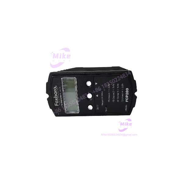
Foxboro FCP280 RH924YA | Field Control Processor 280
Dynamic Product Introduction
The Foxboro FCP280 RH924YA is the controller at the field-control layer of the EcoStruxure Foxboro DCS. This is where control execution actually happens: regulatory loops, sequencing, timing, logic, data acquisition, and alarm processing are handled by the FCP280 rather than by the individual FBM I/O modules. Schneider Electric describes the FCP280 as a distributed field control processor that can also be deployed in a fault-tolerant configuration.
For migration projects, the FCP280 is particularly relevant because Schneider designed it to coexist with and migrate from earlier Foxboro automation hardware. Schneider states that the FCP280 provides twice the capacity and three times the performance of previous controller generations, while retaining compatibility with established Foxboro field infrastructure. That makes it a controller-level component for modernization work where replacing every existing FBM and field connection is not economically attractive.
The architecture is also more flexible than a simple single-CPU controller. The accepts four PIO channels, each representing a separate HDLC fieldbus, and can interface with the Foxboro control network through a 100 Mbps Ethernet connection using the appropriate network adapter. Fiber and copper network adapters are documented options.
One point worth emphasizing for procurement: RH924YA identifies the processor itself. It does not identify the required baseplate, network adapter, fieldbus adapter, or redundant pair hardware. Those are separate components and must be matched to the existing cabinet architecture.
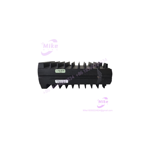
FCP280 RH924YA
Key Technical Specifications
- Manufacturer: Foxboro / Schneider Electric
- Controller:
- Part Number: RH924YA
- Product Type: Field Control Processor
- System: EcoStruxure Foxboro DCS
- Control Functions: Regulatory control, logic, timing, sequential control, data acquisition, alarm detection, and alarm notification
- PIO Channels: 4
- 200 Series FBM Fieldbus: HDLC, 2 Mbps
- Control Network: 100 Mbps Ethernet
- Network Interfaces: Copper or fiber through the appropriate adapter
- Mounting: Device-specific 2-position baseplates
- Module Height: 105 mm (4.13 in) or 116 mm (4.7 in) including mounting lugs
- Module Width: 51.8 mm (2.04 in)
- Module Depth: 147 mm (5.79 in)
- Maximum Single-Module Weight: 0.8 kg (1.76 lb)
- Fault-Tolerant Configuration: Two modules with the appropriate fault-tolerant baseplate/connector arrangement
- Environmental Classification: Class G3 harsh environments
- Cybersecurity: ISA EDSA certified
- Online Upgrade: Supports online image upgrade (OLUG)
Baseplate Compatibility
The is not intended to be installed in an arbitrary Foxboro rack position.
Schneider documents dedicated baseplates, including:
- RH924YL: Horizontal-mounted baseplate
- RH924YF: Vertical-mounted baseplate
- RH100JX: Dual-cable baseplate for horizontal or vertical mounting
- RH924WA: Fiber network adapter
- RH924UQ: Copper network adapter
For fault-tolerant installations, the two processors must occupy the dedicated positions that provide the interconnecting fault-tolerant communication path.
Global Sourcing & Live-Test SOP
Inbound Verification
For , start with identity verification rather than simply powering the module.
Confirm:
- designation
- RH924YA part number
- Foxboro identification
- Hardware/revision information where available
- Processor connector condition
- Baseplate interface condition
- Network adapter interface
- Fieldbus interface
- Housing condition
- Evidence of corrosion, impact, unauthorized repair, or contamination
The supplied listing currently identifies the item as used, with the model and MPN shown as / RH924YA. The listing also states that no returns are accepted, so the procurement risk is materially different from factory-sealed stock with a functional guarantee.
Live Simulation
A meaningful test should reproduce the controller’s actual operating environment.
Recommended sequence:
- Install the in the correct baseplate.
- Connect the appropriate control-network adapter.
- Apply the specified system power.
- Confirm processor initialization and diagnostic status.
- Establish communication with the Foxboro control network.
- Connect a representative fieldbus configuration.
- Verify communication with representative FBM hardware.
- Execute representative control logic.
- Verify I/O acquisition and output handling.
- Monitor controller diagnostics during an extended operating period.
For a fault-tolerant application, test the two processors as a pair rather than qualifying a single and assuming redundancy will work.
Diagnostics
When an fails to communicate, isolate the problem in layers:
Power → baseplate → processor → network adapter → control network → fieldbus → FBM.
Do not immediately replace the processor if the network connection is absent.
The can use either copper or fiber Ethernet through the appropriate adapter. Schneider documents specific adapters and cable requirements, including multimode fiber for the documented fiber connection.
For a suspected fieldbus problem, independently verify each PIO/HDLC path. A controller can be healthy while one fieldbus channel, adapter, cable, or downstream FBM segment is defective.
Final Preparation
Before releasing an as a maintenance spare, record:
- Exact / identification
- Hardware revision
- Firmware/software compatibility information
- Baseplate used during test
- Network adapter type
- Fieldbus configuration
- Processor diagnostic status
- Control-network communication result
- FBM communication result
- Logic execution test
- Test date
Package the processor in ESD-safe material and protect the mating connectors from mechanical impact and contamination.
Field Engineer’s Pitfall Guide
❗ Do not assume is a complete controller installation
identifies the processor module—not the entire controller assembly.
A working installation may also require the appropriate baseplate, network adapter, fieldbus cabling/adapters, power infrastructure, and compatible Foxboro DCS software environment.
A common sourcing mistake is receiving a processor and discovering during cabinet installation that the existing baseplate or network interface is a different generation.
❗ Verify software and image compatibility before swapping processors
An is not just a hardware replacement. The controller participates directly in control execution, fieldbus communications, diagnostics, and the DCS control network.
Before a live replacement, capture the existing controller configuration and verify the target processor’s software/image compatibility.
Schneider specifically documents online image upgrade (OLUG) for the , which is useful during controlled modernization work but should not be interpreted as permission to load arbitrary controller images.
❗ Do not confuse single-module operation with fault-tolerant operation
The can be used as a single processor, but the fault-tolerant implementation uses two processor modules installed in dedicated baseplate positions with an interconnecting fault-tolerant connection.
Replacing one failed processor in a redundant pair therefore requires verification of the pair’s configuration and communication—not merely confirmation that the replacement processor boots.
Intent-Driven FAQ
What is Foxboro ?
is a Foxboro Field Control Processor 280 used in the EcoStruxure Foxboro DCS. It performs regulatory, logic, timing, sequential-control, data-acquisition, and alarm functions.
Is a PLC?
It is better classified as a DCS Field Control Processor rather than a conventional standalone PLC. It operates as part of the Foxboro DCS architecture and communicates with Foxboro FBMs and the plant control network.
How many fieldbus channels does the support?
The supports four PIO channels, representing four separate HDLC fieldbus connections. Schneider documents 2 Mbps operation for the 200 Series FBM fieldbus.
Can operate in a redundant configuration?
Yes. Schneider documents a fault-tolerant configuration using two processor modules mounted in dedicated positions on a suitable baseplate with an interconnecting fault-tolerant connector.
What network does the use?
The connects to the Foxboro control network through 100 Mbps Ethernet using the appropriate copper or fiber adapter. Schneider documents both copper and fiber adapter options.
What is the difference between and its baseplate?
is the processor module. The horizontal RH924YL and vertical RH924YF are separate baseplate part numbers, while RH100JX is the dual-cable baseplate option. They should not be treated as interchangeable catalog identifiers.





