


Description
Foxboro E69F-BI2 | Current-to-Pneumatic Converter, In Stock
Architect’s Product Breakdown
The Foxboro E69F-BI2 operates as a high-precision field-mounted current-to-pneumatic (I/P) signal converter designed to bridge modern electronic control systems with traditional pneumatic final control elements. Its core responsibility involves taking standard direct current signals (such as 4-20 mA) from a controller or PLC and regulating clean instrument air to deliver an exact proportional pressure output (such as 3-15 psi) to drive control valves, dampers, and positioners.
Utilizing a robust galvanometric motor design with generous internal clearances, the E69F series resists typical industrial hazards like dust accumulation and atmospheric corrosion better than traditional voice-coil instruments. Because these units are heavily deployed in critical process loops (such as chemical plants, refineries, and power generation units), locating exact suffix matches (like the B bolted cover and I2 4-20mA to 3-15psi configuration) is mandatory during replacement cycles to ensure proper loop scaling and weather-rating compliance.
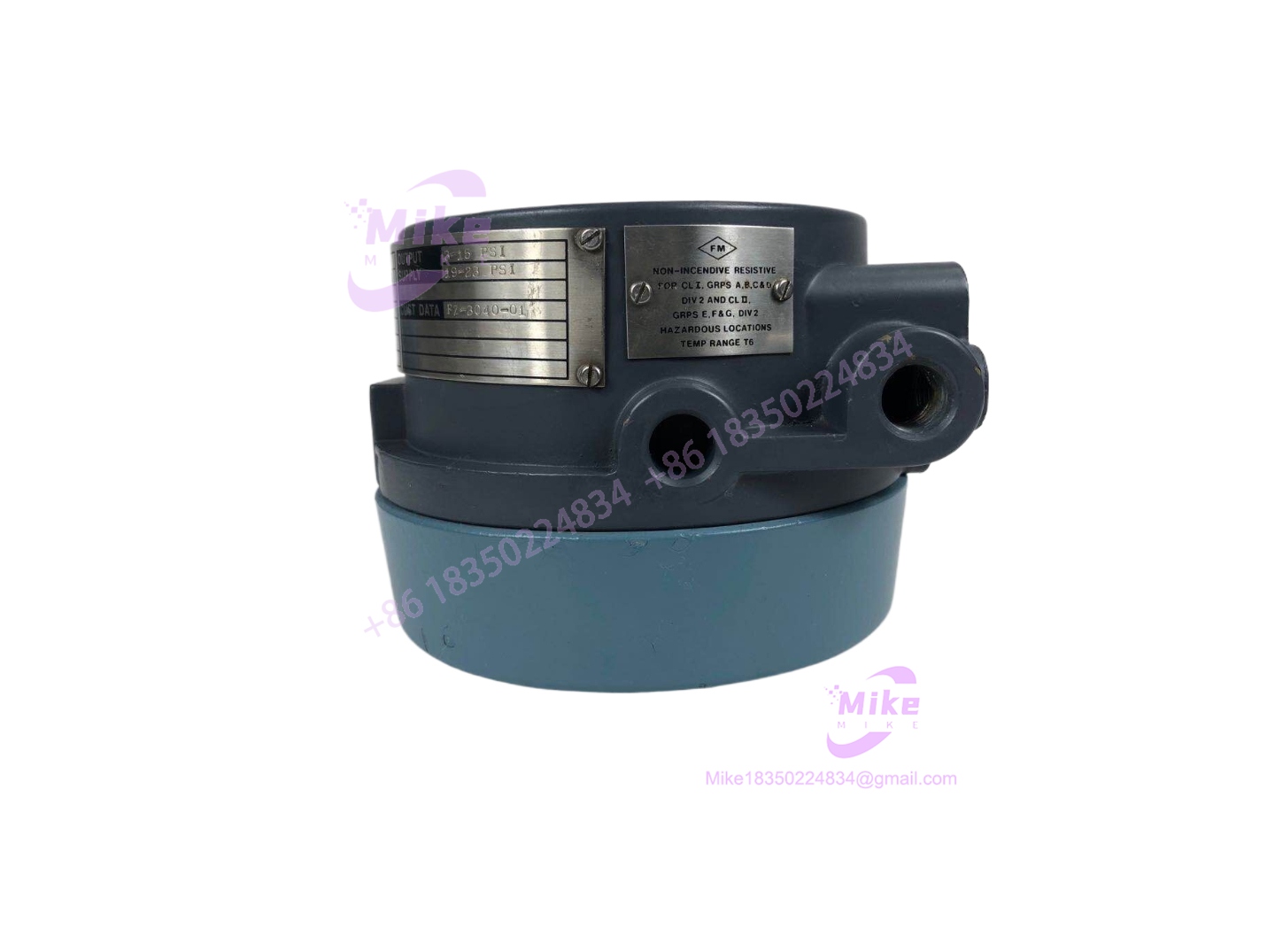
E69F-BI2
Key Technical Specifications
| Parameter | Specification |
| Series | Foxboro E69F Field-Mounted I/P Converter |
| Model / Part Number | E69F-BI2 |
| Enclosure Type (B) | Bolted cover – weatherproof design for general industrial use |
| Input Signal Range (I) | 4 to 20 mA dc (direct or reverse action selectable; ~170 Ω impedance) |
| Output Signal (2) | 3 to 15 psi (20 to 100 kPa or 0.2 to 1.0 bar / kg/cm²) |
| Accuracy | ±1.0% of span |
| Air Supply Requirements | Clean, dry, oil-free instrument air (per standard ISA guidelines) |
| Mounting Options | Surface, valve yoke, or vertical 2-inch (DN 50) pipe mount |
Field Engineer’s Pitfall Guide
- WARNING: Contaminated Instrument Air Supply. Introducing moisture, compressor oil, or particulate debris into the supply ports will clog the internal nozzle and restrictor, causing severe calibration drift or total unit failure.
- WARNING: Ignoring Zero/Span Interaction. Adjusting the zero screw alters the low end of the curve, but changing the span adjustments requires a subsequent zero re-calibration check to maintain loop accuracy.
- WARNING: Hazardous Area Mismatch. Ensure the specific E69F enclosure variant matches the classification of the installation area; standard bolted weatherproof covers (B) are non-explosionproof unless explicitly specified with explosion-proof threaded covers.
- Field Anecdote: I remember a process loop hunting erratically because an I/P converter replacement was subjected to an unconditioned plant air supply containing trace moisture, which froze inside the internal restrictor during an overnight temperature drop.
QA & Testing SOP
- Visual & Origin Verification: Inspect the die-cast housing, cover bolts, O-ring seal, and pneumatic connection ports for thread damage, corrosion, or mechanical wear.
- Live Test Bench Environment: Mount the converter onto a pneumatic calibration bench connected to a regulated instrument air supply and a precision current source/multimeter.
- Calibration & Loop Testing: Apply standard input steps (4 mA, 12 mA, 20 mA) and measure pneumatic output against a calibrated digital pressure gauge to verify 3 to 15 psi linearity and check for hysteresis.
- Anti-Static & Protective Packaging: Cap all pneumatic ports with clean plugs and seal the unit in shock-absorbing packaging to protect external gauges and fittings during shipping.
Technical FAQ
What is the direct modern replacement for the obsolete E69F-BI2?
Schneider Electric/Foxboro typically recommends transitioning to the IP26 Series current-to-pneumatic converters for modern plant retrofits when exact legacy form-fit-function replacements are unavailable.
Can the -BI2 handle reverse-action control loops?
Yes. The unit supports selectable direct or reverse action configuration depending on whether an increasing input signal should increase or decrease the pneumatic output pressure.
What causes sluggish response times in this converter?
Sluggish response is usually caused by restricted instrument air filters, blocked internal restrictor orifices, or a drop in upstream supply air pressure.
Does this unit require a dedicated electrical power supply separate from the signal loop?
No. The -BI2 is loop-powered, drawing its operating power directly from the incoming 4-20 mA control signal loop.





