


Description
Foxboro FBM207 | 16-Channel Isolated Voltage Monitor
Product Introduction
The Foxboro FBM207 is built for a job that looks simple on a wiring diagram but can become difficult in a large DCS cabinet: reliably determining whether field switches, breakers, interlocks, or voltage signals are actually ON or OFF while keeping individual channels electrically isolated.
The module provides 16 isolated and independent digital input channels. Depending on the termination assembly and configured input mode, the FBM207 can monitor 15–60 VDC signals, 120 VAC/125 VDC signals, or 240 VAC signals. This makes the FBM207 particularly useful for switchgear status, motor permissives, breaker feedback, alarm contacts, and other discrete field indications.
The FBM207 communicates with its associated Fieldbus Communications Module or Field Control Processor over a redundant 2 Mbps module Fieldbus. Input filtering can be configured for no filtering or 4, 8, 16, or 32 ms, allowing the engineer to balance contact-bounce rejection against response time. The documented pulse-processing capability supports input frequencies up to 250 Hz without missed pulses.
One point deserves emphasis during procurement: FBM207 is not interchangeable with FBM207b or FBM207c merely because all three have 16 channels. The b and c versions are dedicated contact-sense variants for 24 VDC and 48 VDC field systems respectively. The termination assembly and field voltage must therefore be matched to the exact module variant.
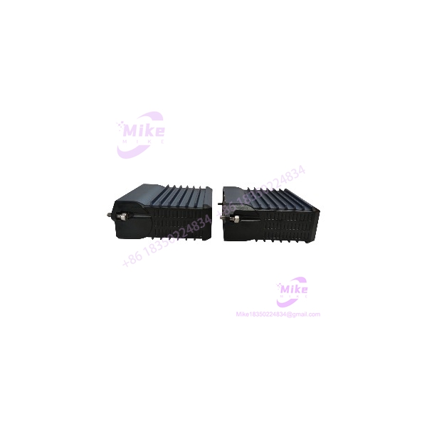
FBM207
Key Technical Specifications
- Model:
- Primary Part Number: P0914TD
- Input Channels: 16
- Channel Type: Isolated and independent digital inputs
- Primary Function: Voltage monitoring / switch input
- 15–60 VDC Input Mode:
- ON-state: 15–60 VDC
- OFF-state: 0–5 VDC
- Typical input current: approximately 1.4 mA at 5–60 VDC
- Maximum ON-state source resistance: 1 kΩ at 15 VDC
- Minimum OFF-state source resistance: 100 kΩ at 60 VDC
- 120 VAC / 125 VDC Mode: Voltage monitoring or switch input, with the appropriate termination assembly
- 240 VAC Mode: Supported with the appropriate 240 VAC termination assembly
- Input Filter: None, 4, 8, 16, or 32 ms
- Pulse Detection: 0–250 Hz without missed pulses under specified conditions
- Fieldbus: Redundant 2 Mbps module Fieldbus
- Fieldbus Connection: Through associated FCM or FCP
- System Supply: 24 VDC +5% / -10%, redundant
- Environmental Rating: ISA S71.04 Class G3
- Operating Temperature: -20 to +70°C
- Relative Humidity: 5–95%, noncondensing
- Mounting: Foxboro 200 Series baseplate / DIN-rail subsystem
- Input Isolation: Channel-isolated architecture
- Termination: Application-specific termination assembly
- Primary Compression Termination: P0916AL for 15–60 VDC voltage monitoring
- Primary Ring-Lug Termination: P0916AN for 15–60 VDC voltage monitoring
- 120/125 V Termination: P0916AM/P0916AP family
- 240 VAC Termination: P0916PH/P0916PJ family
The exact electrical limits depend on the selected termination assembly. Schneider’s current documentation identifies dedicated termination assemblies for 15–60 VDC, 120/125 V, and 240 VAC applications.
Input Signal Architecture
For the low-voltage DC configuration, the treats a field signal between 15 and 60 VDC as the logic ON region, while 0–5 VDC represents the logic OFF region.
The typical input current is approximately 1.4 mA across the specified 5–60 VDC range. Source-resistance limits are also defined, with a maximum of 1 kΩ for the ON state at 15 VDC and a minimum of 100 kΩ for the OFF state at 60 VDC. These figures matter when a long cable run, relay contact, solid-state switch, or auxiliary output is being used as the field signal source.
For 120 VAC/125 VDC and 240 VAC applications, the field termination assembly establishes the appropriate voltage-monitoring or switch-input configuration. This is why a procurement specification should identify both the module and the required termination assembly, rather than ordering the module alone from a generic “16-channel voltage input” description.
Contact-Sense Variants
The family includes two dedicated contact-sense variants.
FBM207b
FBM207b, P0914WH, is the 24 VDC contact-sense version.
- 16 isolated contact-sense inputs
- 24 VDC field contact excitation
- Designed for contact/switch status monitoring
- Compression termination: P0916JS
- Compatible termination family includes RH916XT/P0916PP variants in newer documentation
Radwell identifies P0914WH as FBM207b, 16-input, 24 VDC contact sense, and lists it as discontinued by the manufacturer; this is reseller lifecycle information rather than an OEM statement, so current project substitution should be verified against Schneider documentation.
FBM207c
FBM207c, P0917GY, is the 48 VDC contact-sense version.
- 16 isolated contact-sense inputs
- 48 VDC contact-sense operation
- Designed for higher-voltage DC contact circuits
- Dedicated FBM207c termination assembly
- P0917GY is identified in Foxboro parts references as the 48 VDC contact-sense version.
Do not substitute FBM207b for FBM207c without checking the field voltage. The distinction is electrical, not cosmetic.
Fieldbus and DCS Integration
The communicates with the associated FCM or FCP through the redundant 2 Mbps module Fieldbus.
The module is therefore not a standalone PLC-style remote digital input block. Its input data is transported through the Foxboro DCS Fieldbus architecture and processed by the associated control system.
Input filtering is configurable. A 4 ms setting may be appropriate where response time matters, while longer filtering can suppress mechanical contact bounce and transient changes. For alarm and interlock applications, the filter setting should be reviewed together with the control-block execution period and process permissive logic.
That interaction is easy to overlook during a migration. A field contact can be electrically healthy while the DCS indication still appears delayed because of filtering, logic execution, or downstream alarm processing.
Termination and Wiring
The relies heavily on the termination assembly for its field-voltage configuration.
Documented termination options include:
- P0916AL: Compression termination for , 15–60 VDC voltage monitoring
- P0916AN: Ring-lug termination for , 15–60 VDC voltage monitoring
- P0916AM: Compression termination for , 120/125 V voltage monitoring
- P0916AP: Ring-lug termination for , 120/125 V voltage monitoring
- P0916PH/P0916PJ: 240 VAC monitoring termination options
Newer Schneider documentation also identifies RH-series termination assemblies for these same application classes.
This architecture means that the field voltage should be established before selecting the termination assembly. Ordering “” alone is insufficient when the installation requires a specific 15–60 VDC, 120/125 V, or 240 VAC signal interface.
Global Sourcing & Live-Test SOP
1. Inbound Verification
- Confirm the faceplate marking is .
- Verify the module identification and part number, particularly P0914TD.
- Record serial number and visible hardware revision.
- Inspect the connector, mounting lugs, LEDs, housing, and PCB enclosure for damage.
- Confirm whether the customer requires , FBM207b, or FBM207c.
- Verify the required field voltage before selecting the termination assembly.
- Match the termination assembly to the purchase specification.
- Record OEM documentation and available chain-of-custody information for customs and quality records.
2. Live Simulation
A proper test rack should reproduce the intended voltage-monitoring application.
- Apply representative 15 VDC, 24 VDC, 48 VDC, and 60 VDC signals where applicable.
- Verify OFF-state recognition at 0–5 VDC.
- Test all 16 input channels.
- Exercise contact inputs using controlled switching.
- Test the selected input filter values.
- Verify representative pulse signals within the documented frequency range.
- For 120/125 V or 240 VAC versions, use an appropriately rated isolated test source and the correct termination assembly.
- Confirm Fieldbus communication with the appropriate Foxboro test environment.
3. Diagnostics
- Check module status LEDs.
- Verify Fieldbus communication through the redundant architecture.
- Confirm each channel changes state correctly.
- Monitor for intermittent channel transitions.
- Check contact bounce behavior under several filter settings.
- Record module identification and firmware information where available.
- Compare observed channel response against the configured filter and expected logic execution period.
- Investigate any channel that remains permanently ON or OFF before release.
4. Final Preparation
- Record module serial number and hardware identification.
- Record the exact termination assembly supplied with the module.
- Package the in ESD-safe material.
- Protect the field connector and mounting interface.
- Keep high-voltage termination assemblies physically separated from unrelated low-voltage parts during shipment.
- Clearly identify the voltage configuration when shipping a complete package.
- Do not claim factory-new condition without supporting documentation.
Field Engineer’s Pitfall Guide
❗ Do not assume every accepts the same field voltage. The base uses different termination assemblies for 15–60 VDC, 120/125 V, and 240 VAC applications. The termination assembly is part of the electrical interface.
❗ Do not confuse with FBM207b. P0914TD is the base voltage-monitor module, while P0914WH is FBM207b for 24 VDC contact sensing. The channel count is identical, but the field interface is different.
❗ Do not diagnose a “slow” input without checking the filter setting. The supports configurable filtering of none, 4, 8, 16, or 32 ms. A field signal can be electrically correct while the DCS indication is intentionally delayed by filtering and subsequent logic execution.
Intent-Driven FAQ
1. What is the Foxboro ?
The is a 16-channel isolated voltage-monitor/contact-sense input Fieldbus Module used in Foxboro DCS installations.
2. How many inputs does have?
The provides 16 isolated and independent input channels.
3. What voltage does the accept?
The base supports multiple voltage-monitoring configurations through the appropriate termination assembly, including 15–60 VDC, 120 VAC/125 VDC, and 240 VAC applications. The termination assembly must match the field voltage.





