


Description
Foxboro FBM06 | 4-Channel Pulse / 4-Channel Analog Output
Product Introduction
A pulse-input module has a very different job from a conventional 4–20 mA analog input card. The Foxboro FBM06 is designed to acquire pulse signals from devices such as vortex and turbine flowmeters, solid-state outputs, electromechanical contacts, and similar pulse-producing sensors, while simultaneously providing four analog current outputs.
Foxboro’s I/A Series specification identifies the FBM06 as a Pulse Input, 0 to 20 mA Output Interface Module. It contains four configurable pulse-input channels and four 20 mA DC analog-output channels. The module performs the signal conversion required to interface field devices with the redundant I/A Series Fieldbus.
Each pulse input is independent and isolated. The maximum specified input frequency is 12.5 kHz, making the FBM06 appropriate for frequency-based process measurements where a simple discrete input would not provide sufficient measurement capability.
The four output channels are also isolated and independently controlled, with a specified output range of 0–20.4 mA DC and a maximum load of 735 Ω.
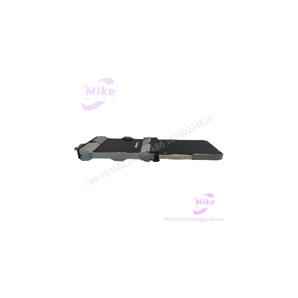
FBM06
Key Technical Specifications
- Manufacturer: Foxboro / Invensys
- Model: FBM06
- System: I/A Series DCS
- Product Type: Pulse Input / 0–20 mA Output Interface Module
- Pulse Inputs: 4 isolated, independent channels
- Analog Outputs: 4 isolated, independent channels
- Pulse Input Frequency: Up to 12.5 kHz
- Input Resistance: 10 kΩ
- Input Device Supply: 24 VDC ±10%, up to 30 mA
- Analog Output Range: 0–20.4 mA DC
- Maximum Output Load: 735 Ω
- Output Compliance Voltage: 18.6 V nominal at 20 mA at field terminals
- Output Accuracy: ±0.05% of span at 25°C
- Output Temperature Coefficient: 100 ppm/°C
- Output Resolution: 12 bits
- Output Settling Time: 100 ms to within 1% of steady state for a 10–90% step
- Communication: Redundant I/A Series Fieldbus
- Input Conversion: Software configurable
- Input Resolution: 12, 13, 14, or 15 bits depending on conversion time
- Input Conversion Times: 0.1, 0.2, 0.5, or 1.0 seconds
- Maximum Power Consumption: 15 W
- Maximum Heat Dissipation: 12 W
- Input/Output Isolation: 600 VAC withstand test between channels and ground for one minute
- Operating Temperature: 0 to 60°C
- Storage Temperature: -40 to +70°C
- Relative Humidity: 5–95%, noncondensing
- Approximate Mass: 1 kg
- Status Indication: Red and green LEDs on the termination connector
- Termination: Available with discrete-wire, direct-connection, and plug-connector arrangements
The official-style I/A Series specification also defines minimum pulse frequencies according to conversion time: 3 Hz for 0.5/1.0-second conversion, 5 Hz for 0.2-second conversion, and 10 Hz for 0.1-second conversion. Maximum pulse frequency is 12,500 Hz.
Global Sourcing & Live-Test SOP
1. Inbound Verification
For a surplus or refurbished FBM06, verify the hardware before energizing it.
- Confirm the module marking is .
- Record the complete part number and revision.
- Photograph the front panel, connectors, and termination interface.
- Inspect the PCB and connector assembly for corrosion or contamination.
- Check for damaged pins or bent contacts.
- Verify the termination assembly is compatible with the .
- Record serial/date information for traceability.
- Compare the received hardware with the customer’s existing module.
Do not substitute an solely because another Foxboro FBM has the same general mechanical footprint.
2. Live Simulation
A proper test should use an I/A Series-compatible test environment.
Recommended checks include:
- Apply the specified module supply.
- Establish redundant Fieldbus communication.
- Inject known-frequency pulse signals into each input.
- Verify pulse-frequency acquisition.
- Test different pulse frequencies within the configured conversion range.
- Verify each 0–20 mA output independently.
- Apply calibrated output loads up to the application’s required range.
- Check output linearity and settling.
- Verify channel isolation.
- Confirm module status LEDs and diagnostic behavior.
For pulse simulation, a calibrated frequency generator is preferable to manually switching contacts because the can operate at frequencies up to 12.5 kHz.
3. Diagnostics
The acceptance procedure should include:
- Fieldbus communication verification.
- Pulse input response.
- Frequency scaling verification.
- Analog output current measurement.
- Output-load verification.
- Channel-to-channel isolation checks.
- Power consumption measurement.
- Thermal observation during extended operation.
A calibrated multimeter can verify the 0–20 mA outputs, while a frequency generator or oscilloscope can provide a controlled pulse-input reference.
4. Final Preparation
Before shipment:
- Clean the module using an electronics-safe process.
- Protect connectors with ESD-safe packaging.
- Record the exact revision and serial information.
- Document test results when testing has actually been completed.
- Package the module against mechanical shock and moisture.
- Clearly distinguish tested, refurbished, used, and untested condition.
Do not claim factory-sealed or factory-tested condition without supporting documentation.
Field Engineer’s Pitfall Guide
❗ Do not mistake for an analog input card:
The is primarily a 4-channel pulse-input / 4-channel analog-output module. It is not the standard Foxboro 0–20 mA input module. In the I/A Series family, FBM01 serves the 0–20 mA input function, while combines pulse inputs with 0–20 mA outputs.
❗ Conversion time changes the usable pulse range:
The module supports several conversion-time settings. At shorter conversion times, the specified minimum pulse frequency increases. A field application that works at 1.0-second conversion may therefore require different configuration when faster updates are selected.
❗ Check the output load before commissioning:
The output channels are specified for loads up to 735 Ω, with approximately 18.6 V compliance at 20 mA. Long cable runs, barriers, indicators, and additional series resistance can consume part of that compliance budget.
Intent-Driven FAQ
What is the Foxboro ?
The is an I/A Series Fieldbus Module providing four pulse-input channels and four isolated 0–20 mA analog-output channels.
How many channels does have?
It has 4 pulse inputs and 4 analog outputs, for a total of eight field channels.
What is the maximum pulse frequency?
The specified maximum pulse-input frequency is 12.5 kHz. The usable minimum frequency depends on the selected conversion time.
Is the a 4–20 mA output module?
Not exactly. Its documented output range is 0–20.4 mA DC. The nominal application range is generally treated as 0–20 mA rather than a dedicated 4–20 mA-only architecture.
What types of devices can provide the pulse input?
The specification identifies applications including vortex and turbine meters, solid-state devices, electromechanical contacts, and other sensors with similar pulse outputs.
Is part of the Foxboro I/A Series?
Yes. Schneider Electric’s I/A Series documentation lists under the Fieldbus Module family as the Pulse Input, 0 to 20 mA Output Interface Module.
Is there a newer replacement for ?
Yes. The I/A Series 100-to-200 upgrade documentation identifies FBM206/FBM206b as the 200 Series upgrade path for , providing four pulse inputs and four 0–20 mA outputs with channel isolation. The exact migration hardware and termination assembly must be checked against the installed system.





