


Description
Foxboro FBM203 | 8-Channel RTD Input Module
Product Introduction
Temperature measurement problems rarely begin with the controller. More often, the failure is somewhere between the RTD element, extension wiring, termination assembly, and analog conversion channel. The Foxboro FBM203 is designed for that exact interface layer, providing eight isolated RTD measurement channels for the I/A Series 200 DCS.
The standard FBM203 accepts RTD signals over a 0–320 Ω resistance range and supports 2-wire or 3-wire RTD sensors. Each input is galvanically isolated from the other channels and from ground. Schneider specifies independent Sigma-Delta conversion for every channel, allowing new analog values to be generated every 25 ms with a configurable integration period for noise reduction.
The FBM203 family also includes FBM203b, FBM203c, and FBM203d variants. These are not cosmetic revisions: FBM203b expands the resistance range to 0–640 Ω, FBM203c is designed for 0–30 Ω copper RTDs, and FBM203d supports the 0–320 Ω range with a 4-wire RTD configuration.
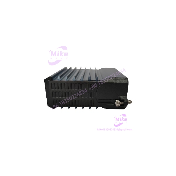
FBM203
Key Technical Specifications
- Model: FBM203
- Product type: RTD Input Module
- System: Foxboro I/A Series 200
- Number of input channels: 8
- Channel architecture: Isolated and independent
- Input type: Resistance Temperature Detector
- Standard input range: 0–320 Ω
- Full-scale count: 64,000 counts at 320 Ω
- Minimum overrange value: 327.675 Ω at 65,535 counts
- Sensor current: 0.19 mA DC nominal
- Supported wiring: 2-wire or 3-wire RTD
- Typical platinum sensor: 100 Ω nominal at 0°C
- Typical nickel sensor: 235 Ω nominal at 0°C
- Supported sensor families: Platinum DIN, Platinum SAMA, Platinum IEC, Nickel SAMA
- Analog accuracy including linearity: ±0.03% of span
- Accuracy temperature coefficient: ±50 ppm/°C
- A/D conversion: Independent Sigma-Delta converter per channel
- New analog value rate: Every 25 ms
- Integration period: Software configurable
- Common-mode rejection: >125 dB at 50/60 Hz
- Normal-mode rejection: >95 dB at 50/60 Hz
- Lead resistance: 50 Ω maximum per lead for FBM203/203b
- Communication: Redundant 2 Mbps module Fieldbus
- Supply: 24 VDC, +5% / -10%, redundant
- Maximum power consumption: 3 W
- Maximum heat dissipation: 3 W
- Input/channel isolation withstand: 600 VAC for one minute
- Operating temperature: -20 to +70°C
- Storage temperature: -40 to +70°C
- Operating humidity: 5–95%, noncondensing
- Operating altitude: -300 to +3,000 m
- Storage altitude: -300 to +12,000 m
- Vibration: 0.75 g, 5–500 Hz
- Environmental rating: ISA S71.04 Class G3
- Approximate module weight: 284 g
- Module dimensions: 102 × 45 × 104 mm
- Height including mounting lugs: 114 mm
- OEM module part number: RH914SV
These specifications are based on Schneider Electric’s PSS 41H-2S203, Rev. B, dated May 2025.
RTD Input Architecture
The provides eight independent RTD channels. Each channel measures sensor resistance and converts it into a temperature value through the I/A Series analog-input application.
For the standard :
- Measurement range: 0–320 Ω
- Sensor excitation: 0.19 mA DC nominal
- 100 Ω platinum RTD: approximately 100 Ω at 0°C
- 235 Ω nickel RTD: approximately 235 Ω at 0°C
The module supports 2-wire and 3-wire variable-resistance temperature sensors. With a 2-wire RTD, there is no correction for lead resistance or changes in lead resistance with temperature.
That makes the wiring configuration important. For long cable runs or higher-accuracy temperature loops, the 3-wire arrangement should be checked against the original engineering design rather than treating the RTD as a simple two-terminal resistor.
Family Variants
The suffix determines the electrical measurement range:
- — 0–320 Ω; standard RTD input
- FBM203b — 0–640 Ω; extended resistance range
- FBM203c — 0–30 Ω; copper RTD applications
- FBM203d — 0–320 Ω; 4-wire RTD input configuration
The standard and FBM203b have a maximum specified lead resistance of 50 Ω per lead, while the FBM203c uses a 10 Ω maximum per lead. For FBM203d, the total specified lead resistance is 50 Ω and lead imbalance does not affect accuracy.
Do not substitute these variants solely because the front-panel hardware appears similar.
Signal Conversion and Accuracy
Each input channel uses its own Sigma-Delta A/D conversion path. The module can provide new analog values every 25 ms, while a software-configurable integration period averages measurements to suppress process noise and power-line interference.
For the standard , the documented analog accuracy, including linearity, is:
±0.03% of span
The specified accuracy temperature coefficient is ±50 ppm/°C. Common-mode rejection exceeds 125 dB at 50/60 Hz, while normal-mode rejection exceeds 95 dB at 50/60 Hz.
For temperature applications, these figures matter because an RTD system can otherwise look like a sensor problem when the actual issue is electrical noise, extension-lead imbalance, or poor termination.
Fieldbus Communication
The communicates with its associated Fieldbus Communications Module (FCM) or Field Control Processor (FCP) through the redundant 2 Mbps module Fieldbus.
The module can communicate through either Fieldbus path, A or B. If one communication path becomes unsuccessful or is switched at the system level, the continues communication over the active path.
The practical architecture is:
RTD sensor → termination assembly → → redundant 2 Mbps Fieldbus → FCM/FCP → Foxboro DCS
The itself therefore should be evaluated as part of the complete I/O subsystem, not as an isolated temperature transmitter.
Termination Assemblies
Schneider documents several termination options for .
For the standard :
- RH916XJ — DIN-rail compression-screw termination assembly
- P0917JM — ring-lug termination assembly
- RH924WN — baseplate-mounted compression termination assembly for paired channels
The baseplate-mounted assembly can provide two sets of eight channels for modules installed in paired slots.
The DIN-rail arrangement uses a removable termination cable between the termination assembly and the FBM baseplate. Termination cables are available in lengths up to 30 m / 98 ft, with polyurethane or LSZH cable materials.
For the standard , the termination cable is Type 1.
100 Series Migration
The has a useful legacy migration relationship.
Schneider documents the termination architecture as supporting the functionality of the 100 Series FBM03A when used with a 3-wire RTD input. FBM203c similarly supports FBM33A functionality, while FBM203d addresses the FBM03B/FBM33B configurations for 2-wire or 4-wire RTD applications.
This makes relevant when replacing older Foxboro RTD hardware during a 100 Series to 200 Series migration.
However, the migration should still verify:
- Existing RTD type
- 2-wire versus 3-wire wiring
- Channel scaling
- Existing termination assembly
- Termination cable
- Baseplate arrangement
- FCM/FCP compatibility
- DCS database configuration
- Alarm and range settings
Global Sourcing & Live-Test SOP
Inbound Verification
For an received from surplus or legacy inventory, verify:
- Exact model:
- OEM marking
- Module part number: RH914SV
- Serial number
- Hardware revision
- Front-panel LED condition
- Connector condition
- Baseplate interface
- Evidence of corrosion or contamination
- Matching termination hardware
The current Schneider PSS identifies RH914SV as the module part number.
Live Simulation
A proper incoming test should use calibrated resistance simulation rather than simply applying power.
Recommended test points include:
- Low-range resistance
- Representative operating resistance
- Mid-scale resistance
- High-range resistance
- All eight channels
- 2-wire configuration where applicable
- 3-wire configuration where applicable
Verify:
- Temperature scaling
- Channel stability
- A/D conversion
- Integration behavior
- Fieldbus data transmission
- Diagnostic status
- Redundant Fieldbus communication
A precision resistance decade box or calibrated RTD simulator is appropriate for this test. A Fluke-class precision measurement instrument can be used to verify the simulator and associated wiring.
Diagnostics
Check:
- Module status LEDs
- Fieldbus A
- Fieldbus B
- Individual channel values
- Channel scaling
- Sensor wiring
- Lead resistance
- Termination assembly
- Baseplate connector
- Diagnostic indications
A module that communicates correctly but produces a systematic temperature offset should not automatically be classified as healthy. Check sensor type, wiring configuration, lead resistance, and DCS scaling first.
Final Preparation
Before shipment:
- Record serial number
- Record hardware revision
- Record test resistance values
- Record tested channel configuration
- Photograph module identification
- Protect connectors against ESD and impact
- Identify the exact RTD variant
- Document the termination assembly used during testing
Do not represent a surplus as factory tested without supporting documentation.
Field Engineer’s Pitfall Guide
❗ Do not ignore lead resistance.
The standard permits up to 50 Ω per lead, but imbalance in the extension leads reduces accuracy. A 3-wire RTD arrangement exists for a reason; replacing it with a casually wired 2-wire sensor can introduce a measurable temperature error.
❗ Do not confuse with FBM203b or FBM203c.
The standard measures 0–320 Ω. FBM203b extends the range to 0–640 Ω, while FBM203c uses a 0–30 Ω range for copper RTDs. The wrong suffix can produce an electrically incorrect measurement even though the module family is the same.
❗ Do not treat the 600 VAC isolation rating as an operating voltage rating.
The 600 VAC specification is a one-minute withstand test. Schneider explicitly states that the channels are not intended for permanent connection to hazardous-voltage circuits and warns against applying voltages beyond the published input ranges.
Migration and Replacement Considerations
The family remains documented in Schneider Electric’s current Foxboro DCS PSS library under PSS 41H-2S203. Schneider’s documentation identifies /b/c/d as Platinum/Nickel/Copper RTD input modules.





