


Description
Foxboro FBM205 | Redundant 0 to 20 mA Analog I/O Module
Product Introduction
When an analog loop is part of a control function that cannot tolerate a single I/O module failure, ordinary channel duplication is not enough. The Foxboro FBM205 is designed specifically for this condition: two FBM205 modules operate as a redundant pair, with the same field I/O connected through a common termination arrangement.
Each FBM205 contains four analog inputs and four analog outputs. The redundancy is implemented at the module level rather than by simply adding extra spare channels. Both modules participate in the I/O operation, while the Foxboro control blocks validate the redundant signals and maintain the output function when one module fails.
The FBM205 accepts typical 4–20 mA transmitter signals and self-powered 4–20 mA sources. Its four analog outputs provide 0–20 mA signals to external loads. Each channel is galvanically isolated, while the redundant pair shares the field connection through the specified redundant adapter. That distinction matters during cabinet design: redundant input or output pairs connected through the common field I/O connector are not isolated from each other.
For maintenance, the architecture is particularly useful. Schneider specifies that either module can be removed and replaced without disturbing the field input/output signals, power, communications cabling, or the operating healthy module. This makes the FBM205 relevant to high-availability DCS installations where planned maintenance and fault replacement need to occur without taking the associated analog loop offline.
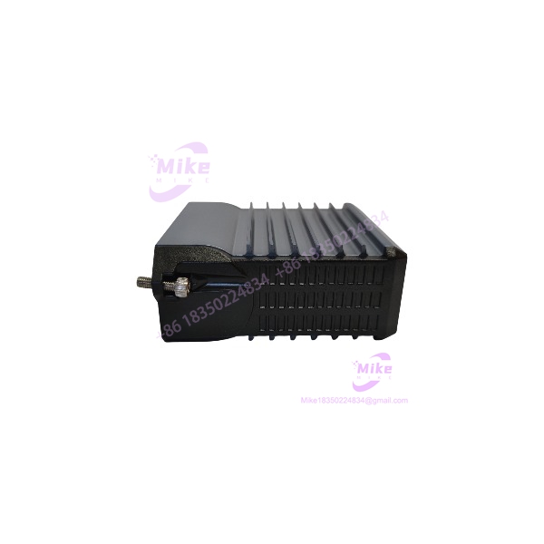
FBM205
Key Technical Specifications
- Model:
- Product Type: Redundant 0 to 20 mA I/O Interface Module
- Analog Inputs: 4 redundant 0 to 20 mA DC channels
- Analog Outputs: 4 redundant 0 to 20 mA DC channels
- Per-Channel Range: 0 to 20.4 mA DC
- Input Accuracy: ±0.3% of span, including tolerance of the redundant-adapter sense resistor
- Output Accuracy: ±0.05% of span
- Input Temperature Coefficient: ±50 ppm/°C
- Input Impedance: 60 Ω nominal
- Input Conversion: Independent Sigma-Delta A/D conversion per channel
- Input Integration Period: Software configurable
- Input Common-Mode Rejection: >100 dB at 50/60 Hz
- Input Normal-Mode Rejection: >95 dB at 50/60 Hz
- Output Load: 750 Ω maximum
- Output Processing Delay: 30 ms maximum
- Output Resolution: 13 bits
- HART Compatibility: Yes
- Module Fieldbus: Redundant 2 Mbps
- Fieldbus Paths: A and B
- Power Input: 24 VDC +5% / -10%, redundant
- Power Consumption: 10 W maximum for redundant pair
- Heat Dissipation: 7 W maximum for redundant pair
- Module Weight: Approximately 284 g
- Module Dimensions: 102 × 45 × 104 mm; 114 mm including mounting lugs
- Operating Temperature: -20 to +70°C (-4 to +158°F)
- Storage Temperature: -40 to +70°C (-40 to +158°F)
- Relative Humidity: 5–95%, noncondensing
- Operating Altitude: -300 to +3,000 m
- Storage Altitude: -300 to +12,000 m
- Vibration: 0.75 g, 5–500 Hz
- Environmental Rating: ISA S71.04 Class G3 harsh environment
- Module Part Number: RH914XG
- Redundant Adapter: RH916NN
- Termination Cable: Up to 30 m
- Cable Material: Polyurethane or LSZH
- Termination Cable Connector: 25-pin male D-subminiature
Redundant I/O Architecture
The uses a pair of modules to provide redundant analog I/O.
For analog outputs, the Foxboro AOUTR control block sends identical output writes to both modules during each execution cycle. This continuously exercises the Fieldbus and module logic. If one module is detected as failed, its output is driven to 0 mA while the healthy module continues supplying the required current to the field loop.
For analog inputs, the AINR control block reads both redundant channels and validates their information. The objective is not merely to have a spare card sitting idle; both modules are involved in ongoing diagnostics and signal processing.
The input loop power is also redundant. Power from the two modules is diode-OR’d through the redundant adapter, while individual channel power supplies provide redundant power to the input current loops. Schneider also provides test points on the redundant adapter for periodic measurement of transmitter power-supply output.
This is the important procurement distinction:
FBM204 = conventional 4 AI + 4 AO analog I/O module.
= redundant 4 AI + 4 AO analog I/O architecture using a matched module pair and redundant adapter.
Do not substitute one for the other merely because the channel counts appear similar.
Analog Input Performance
Each input accepts a 0–20 mA signal, including common 4–20 mA transmitters and self-powered 4–20 mA sources.
The specified input impedance is 60 Ω nominal, with a documented compliance voltage of approximately 22.8 VDC. Actual maximum field-device distance depends on transmitter compliance capability, conductor resistance, and voltage drop at the field device. A long cable run therefore needs a proper loop-budget calculation rather than a simple distance comparison.
Each input channel uses its own Sigma-Delta conversion process. New analog readings are available every 25 ms, while the integration period can be configured in software to average readings and reduce process noise and power-line frequency interference.
The input side provides greater than 100 dB common-mode rejection at 50/60 Hz and greater than 95 dB normal-mode rejection at 50/60 Hz.
Analog Output Performance
The four analog outputs produce 0–20 mA signals and can drive loads up to 750 Ω.
Output resolution is 13 bits, with a maximum processing delay of 30 ms. Each output channel is galvanically isolated, current limited, and voltage regulated. Normal output current is limited to approximately 25 mA; Schneider notes that an output FET short could permit current to increase to approximately 35 mA.
The is electrically compatible with standard HART signals. Its output channels meet the impedance requirements for a HART high-impedance device and can operate in a HART loop without interfering with HART signaling between the field device and handheld communicator.
When a FoxCom or HART transmitter is used with the , Schneider specifies a 200 Ω in-line resistor, RH902VY, in series with the transmitter.
Isolation and Electrical Safety
Each individual channel is galvanically isolated from other channels and ground.
The module withstands 600 VAC for one minute between a channel and ground or between one channel and another channel during the specified isolation test. This is an isolation-withstand specification, not a permissible operating voltage. The field channels are not intended for permanent connection to hazardous-voltage circuits, and Schneider explicitly warns against applying voltages beyond the published input range.
There is one subtle point that procurement engineers should not overlook: redundant input or output pairs are connected through the common field I/O connector and therefore are not isolated from each other. The individual channels are isolated by design, but the redundant pair has a shared field connection architecture.
Fieldbus and Maintenance Architecture
The communicates with the associated Fieldbus Communications Module or Field Control Processor through a redundant 2 Mbps module Fieldbus.
Communication can occur through Fieldbus path A or path B. If one path is unsuccessful or switched at the system level, the continues communication over the active path.
The two redundant modules must occupy adjacent baseplate positions:
- Positions 1 and 2
- Positions 3 and 4
- Positions 5 and 6
- Positions 7 and 8
A RH916NN redundant adapter is installed across the two adjacent termination-cable connectors so that the redundant pair uses a single termination-cable connection to the field termination assembly.
The system configuration software and monitoring tools can display the redundant modules as separate modules. The functional redundancy is provided through the associated control blocks rather than by treating the pair as a single physical module.
Termination and Wiring
Schneider specifies DIN-rail-mounted, electrically passive termination assemblies for field wiring.
The documented termination options include:
- RH916XL: Compression-type termination assembly
- P0917JP: Ring-lug termination assembly
- RH917QW: Termination assembly with output bypass jacks
- RH916NN: Redundant adapter required for redundant configuration
The RH917QW termination assembly provides built-in bypass jacks for each output channel. These can accept a bypass plug from the Foxboro Output Bypass Station or another external 20 mA source when maintaining output signals during module maintenance is required.
Termination cables are available up to 30 m (98 ft), allowing the termination assembly to be installed inside the main enclosure or in an adjacent enclosure. Both polyurethane and LSZH cable constructions are documented.
Global Sourcing & Live-Test SOP
1. Inbound Verification
- Confirm the physical marking reads .
- Verify the module part number as RH914XG where the identification label is accessible.
- Record serial number and hardware identification.
- Inspect the connector, mounting lugs, enclosure, LEDs, and label condition.
- If supplied as a redundant set, verify that both modules are actually units.
- Confirm the presence and correct part number of the RH916NN redundant adapter when required.
- Match the termination assembly to the customer’s existing cabinet wiring.
- Preserve serial-number photographs and available OEM paperwork for traceability.
2. Live Simulation
A meaningful test should use a dedicated Foxboro-compatible test arrangement rather than a simple power-on inspection.
- Simulate 4 mA, 12 mA, and 20 mA input conditions.
- Test all four input channels.
- Test all four analog outputs against representative loads.
- Verify output response at multiple current setpoints.
- Exercise both modules in a redundant pair.
- Verify AINR input validation where the appropriate control environment is available.
- Verify AOUTR output handling where the appropriate control environment is available.
- Confirm redundant Fieldbus communication on paths A and B where the test rack supports it.
- Check HART loop behavior when HART instrumentation is part of the intended application.





