


Description
Foxboro FBM202 | 8-Channel Thermocouple/mV Input
Product Introduction
Temperature loops are unforgiving during a DCS migration. A module can fit the baseplate, communicate normally, and still deliver bad process data if the thermocouple type, reference-junction arrangement, or termination assembly is wrong.
The Foxboro FBM202 is designed specifically for that measurement layer. It provides eight isolated and independent thermocouple/mV inputs, with each channel using independent Sigma-Delta conversion. A separate isolated RTD channel provides reference-junction compensation for the thermocouple inputs.
The FBM202 supports common thermocouple types including B, E, J, K, N, R, S, and T, as well as other millivolt signals. Each thermocouple/mV input also provides upscale burnout detection.
For legacy Foxboro installations, the FBM202 has an important migration role: Schneider documents it as providing functionality formerly supplied by the 100 Series FBM02. Existing FBM02 field wiring can be retained through appropriate termination assemblies or a termination assembly adapter, which can materially simplify a 100-to-200 Series migration.
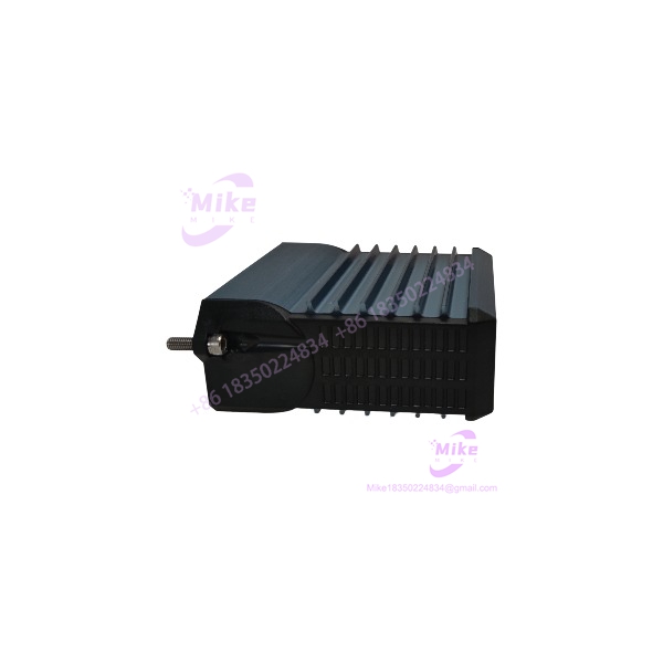
FBM202
Key Technical Specifications
- Model: FBM202
- Product type: Thermocouple/mV Input Module
- System: Foxboro I/A Series 200
- Number of thermocouple/mV inputs: 8
- Input channels: Isolated and independent
- Reference-junction compensation: 1 isolated channel
- Reference-junction sensor: 4-wire 100 Ω platinum RTD
- RTD standard: IEC 751, Class B
- Input range: -10.5 to +69.5 mVDC
- Full-scale module range: 71.419 mV = 65,535 raw counts
- Typical thermocouple types: B, E, J, K, N, R, S, T
- Thermocouple burnout detection: Full upscale value
- Millivolt input accuracy: ±0.03% of span, ±24 μV at 25°C
- RTD channel accuracy: ±0.03% of span
- RTD reference-junction conformity: ±0.25°C
- RTD reference-junction measurement accuracy: ±0.50°C when using the RTD integral to Foxboro-supplied termination assemblies
- Accuracy temperature coefficient: ±50 ppm/°C
- Differential input impedance: 10 MΩ
- Common-mode voltage: Up to 30 VAC or 60 VDC
- A/D conversion: Independent Sigma-Delta converter per channel
- New analog readings: Every 25 ms capability
- Integration period: Software configurable
- Input channel isolation: Galvanically isolated channel-to-channel and channel-to-ground
- Isolation withstand: 600 VAC for one minute
- Communication: Redundant 2 Mbps module Fieldbus
- Supply voltage: 24 VDC, +5% / -10%, redundant
- Maximum power consumption: 3 W
- Maximum heat dissipation: 3 W
- Operating temperature: -20 to +70°C
- Storage temperature: -40 to +70°C
- Relative humidity: 5–95%, noncondensing
- Operating altitude: -300 to +3,000 m
- Storage altitude: -300 to +12,000 m
- Vibration: 0.75 g, 5–500 Hz
- Environmental classification: ISA S71.04 Class G3
- Module weight: Approximately 284 g
- Module dimensions: 102 mm high × 45 mm wide × 104 mm deep
- Height including mounting lugs: 114 mm
- OEM module part number: RH926EQ
These specifications are from Schneider Electric’s PSS 41H-2S202, Rev. B.
Thermocouple and mV Input Architecture
The FBM202 accepts eight thermocouple/mV signals. Each input is electrically isolated from the other channels and from ground, reducing the impact of ground-potential differences between field instruments.
The module’s documented input range is -10.5 to +69.5 mVDC, while 71.419 mV corresponds to the 65,535-count full range. That distinction matters when evaluating raw-count scaling or unusual millivolt applications.
Thermocouple support includes:
- Type B
- Type E
- Type J
- Type K
- Type N
- Type R
- Type S
- Type T
- Other compatible millivolt signals
Thermocouple burnout detection drives the affected input to the documented full upscale value.
Reference-Junction Compensation
The does not simply read the thermocouple voltage and stop there.
It incorporates an isolated reference-junction compensation channel using a 4-wire, 100 Ω platinum RTD conforming to IEC 751 Class B. The RTD is integrated into the appropriate termination assembly, where it measures terminal temperature for thermocouple compensation.
The PSS specifies:
- RTD reference-junction conformity: ±0.25°C
- RTD reference-junction measurement accuracy: ±0.50°C when using the RTD internal to Foxboro-supplied termination assemblies
- RTD thermocouple conformity: ±0.25°C
This is why the termination assembly should be treated as part of the measurement architecture, not merely as a convenient wiring terminal.
Signal Conversion and Noise Management
Each channel uses an independent Sigma-Delta converter. The module can provide new analog readings every 25 ms, while a configurable integration period averages converted values to reduce process noise and power-line interference.
This is useful when commissioning temperature loops with noisy field wiring. A fast conversion setting may be appropriate for responsive measurement, while longer integration can provide additional noise averaging where the process itself changes slowly.
The also executes an Analog Input application program supporting configurable integration time and Rate of Change Limits.
Fieldbus Communication
The communicates with its associated Fieldbus Communications Module (FCM) or Field Control Processor (FCP) through the redundant 2 Mbps module Fieldbus. It accepts communication from either Fieldbus path, A or B. If one path is unavailable or switched at the system level, communication continues through the active path.
The practical signal chain is:
Thermocouple → termination assembly → → redundant 2 Mbps Fieldbus → FCM/FCP → Foxboro DCS
This architecture should be verified before replacing an in an existing cabinet.
Termination Assemblies
Schneider documents multiple termination options for .
For a single , the documented DIN-rail termination assemblies include:
- RH916XH — compression-terminal type
- P0917JL — ring-lug type
A baseplate-mounted termination assembly, RH928CN, supports two sets of eight thermocouple/mV channels and therefore accommodates two modules in paired baseplate positions.
The termination assemblies are electrically passive. The DIN-rail configuration uses a removable termination cable between the termination assembly and the FBM baseplate. Cable lengths are available up to approximately 30 m / 98 ft.
100 Series FBM02 Migration
This is one of the most important procurement details for .
Schneider explicitly states that when an replaces the 100 Series FBM02, the can use the appropriate existing FBM02 termination assemblies for the field I/O wiring. Alternatively, a Termination Assembly Adapter (TAA) can be used.
That makes particularly relevant for plants migrating from older 100 Series hardware while trying to minimize field rewiring.
However, this should not be interpreted as a universal plug-and-play replacement. The engineering review still needs to confirm:
- Existing FBM02 configuration
- Thermocouple type
- Termination assembly
- Termination cable
- Baseplate architecture
- FCM/FCP compatibility
- Channel scaling
- Application configuration
- DCS database mapping
Global Sourcing & Live-Test SOP
Inbound Verification
For an acquired through surplus or legacy inventory, verify:
- Exact model:
- OEM markings
- Module part number: RH926EQ
- Serial number
- Hardware revision
- Connector condition
- Baseplate interface
- Front-panel LED condition
- Signs of corrosion, contamination, or physical damage
- Matching termination assembly
The current Schneider PSS identifies RH926EQ as the module part number.
Live Simulation
A proper test should use a calibrated thermocouple simulator or precision millivolt source.
Recommended verification:
- Test all eight channels
- Simulate representative thermocouple/mV values
- Verify zero and mid-range values
- Check upscale burnout behavior
- Confirm thermocouple type configuration
- Verify reference-junction compensation
- Check analog scaling
- Verify integration settings
- Confirm Rate of Change Limit behavior where configured
- Test redundant Fieldbus communication paths
Do not treat a green status LED as proof of analog accuracy.





