

Description
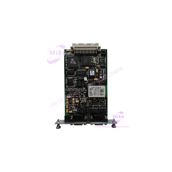
Eaton MPB2-TP | Communication Module Key Spec and Availability
Architect’s Product Breakdown
The Eaton MPB2-TP operates as a high-integrity communication interface designed to integrate plant-floor instrumentation into larger distributed control systems. Within legacy and modern automation hierarchies, this specific hardware model acts as a direct conduit for deterministic data exchange, handling fieldbus traffic without overloading the primary processor backplane. Engineering teams frequently deploy this unit when expanding legacy I/O drops or retrofitting older control loops that rely on deterministic fieldbus architectures.
Integration requires strict adherence to network topology rules, particularly concerning termination resistors and cable shielding. Firmware version alignment between the host controller and the module remains non-negotiable; minor revisions can trigger silent dropouts if baud rate handshakes fail. By isolating the field network traffic from internal control execution cycles, the unit preserves deterministic scan times and prevents communication jitter from propagating up to the supervisory layer.
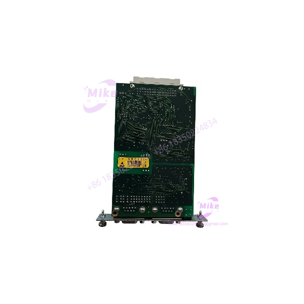
MPB2-TP
Key Technical Specifications
| Parameter | Specification |
| Manufacturer | Eaton |
| Part Number | MPB2-TP |
| Module Type | Fieldbus Communication Interface |
| Supported Protocol | Profibus DP |
| Physical Interface | RS-485 |
| Transmission Speed | 9.6 kbps up to 12 Mbps (Auto-detect) |
| Maximum Node Capacity | Up to 126 nodes per segment |
| Maximum Bus Length | 1200 meters (dependent on baud rate and cable gauge) |
| Nominal Operating Voltage | 24 VDC |
| Current Consumption | 200 mA typical |
| Operating Temperature Range | 0°C to 60°C |
| Enclosure Protection | IP20 |
Field Engineer’s Pitfall Guide
- WARNING: Baud Rate Mismatch on Legacy Lines. Failing to verify the master controller’s configuration against the slave node settings will cause immediate bus timeouts. If automatic baud rate detection fails, force the network speed manually through the engineering software.
- WARNING: Shield Grounding Failures. Leaving the RS-485 drain wire ungrounded or multi-grounded introduces ground loops that corrupt telegram packets in high-noise environments near variable frequency drives. Terminate the shield strictly at one end according to standard industrial practices.
- Anecdotal Warning: I have seen commissioning teams spend three consecutive night shifts troubleshooting intermittent dropouts on an assembly line, only to discover that a maintenance technician swapped an old hardware model with a newer revision without updating the GSD file in the engineering station. Always import the exact GSD revision matching the physical device before downloading hardware configurations.
QA & Testing SOP (Transparency)
- Visual & Origin Inspection: Every unit undergoes microscopic verification of OEM holographic seals, date codes, and pin alignments to eliminate counterfeit risks.
- Live Test Environment: The module is powered up on a dedicated hardware test bench simulating an active fieldbus rack configuration.
- Diagnostics & Handshake: Technicians execute full telegram traffic simulation tests, verifying error-free frame transmission at maximum specified baud rates across the RS-485 interface.
- Firmware Logging & Packaging: Operating firmware revisions are documented on the inspection sheet, followed by ESD-safe shielding and anti-static vacuum sealing prior to warehouse dispatch.
Technical FAQ
Can I hot-swap this module while the process is running?
No. The backplane bus design does not support live insertion or removal under power. Removing the module while energized risks backplane arc damage and processor fault trips.
What is the maximum allowable cable distance for this communication interface?
The maximum segment length reaches 1200 meters at lower transmission speeds, but this distance scales down significantly as you approach the 12 Mbps limit. Repeaters must be used for runs exceeding physical limits.
Does the unit retain its configuration parameters after a power loss?
Yes. Network addresses and communication parameters are stored in non-volatile flash memory, preserving configuration data indefinitely without relying on backup batteries.





