

Description
Honeywell FC-SDI-1624 | 24VDC Safety Digital Input
Dynamic Product Introduction
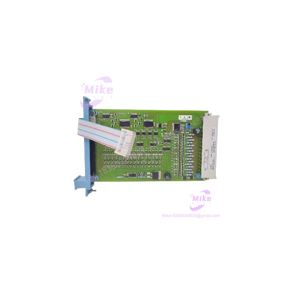
The FC-SDI-1624 is the kind of module that gets incorrectly reduced to “16-channel 24V digital input.” That description is electrically recognizable but misses the procurement issue: this is Safety Manager safety I/O, not a generic PLC DI card.
Honeywell specifies 16 input channels, a maximum input voltage of 36 VDC, approximately 7 mA input current at 24 VDC, and defined HIGH/LOW thresholds. The module also has a 24 VDC solid-state output associated with its architecture, with a maximum specified current of 450 mA and short-circuit protection.
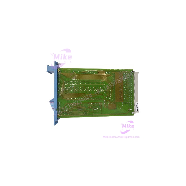
The FC designation matters. Honeywell distinguishes FC modules from FS modules by coating; the TÜV documentation identifies FC-SDI-1624 as the conformal-coated variant. That makes the exact catalog number important when replacing an installed module. FC-SDI-1624 should not simply be substituted with an FS-SDI-1624 because both happen to share the same basic SDI-1624 function.
For maintenance teams, this module is most useful as a controlled replacement for an existing Safety Manager installation where the I/O architecture, application configuration, and qualified hardware revision are already known.
FC-SDI-1624
Key Technical Specifications
- Manufacturer: Honeywell
- Model: FC-
- Product Type: Safe Digital Input Module
- System: Honeywell Safety Manager
- Configuration: Conformal-coated FC version
- Safety I/O Type: Digital input
- Input Channels: 16
- Nominal Input Voltage: 24 VDC
- Maximum Input Voltage: 36 VDC
- Input Current: 7 mA at 24 VDC
- Input HIGH: >15 VDC
- Input LOW: <9 VDC, with input current below 2 mA
- Typical Input Delay: 10 ms
- Maximum Load Capacitance: 100 nF
- 5 VDC Power Requirement: 8 mA
- 24 VDC Internal Supply: 110 mA
- 24 VDC External Input Current: 110 mA
- 5 VDC Ripple Limit: <0.5 Vp-p, 0–360 Hz
- Associated Solid-State Output: 24 VDC, short-circuit protected
- Maximum Solid-State Output Current: 450 mA
- Maximum Output Load Capacitance: 32 µF
- Output Voltage Drop: <1.5 V at 450 mA
- Mechanical Space: 4 TE × 3 HE, equivalent to 4 HP × 3U
- Approvals Listed by Honeywell: CE, TÜV, UL, CSA, FM
These values are taken from Honeywell’s Safety Manager Hardware Reference rather than generic reseller specifications.
Part-Number and Revision Note
The TÜV release documentation identifies multiple FC- conformal-coated revisions, including:
- CC V1.0 — Part Number 3432100
- CC V1.1 — Part Number 3432110
Both are listed as valid Safety Manager hardware in the referenced certification release list.
That is why a purchasing department should record the complete module label and revision, rather than purchasing solely against the family number FC-.
Global Sourcing & Live-Test SOP
1. Inbound Verification
For FC-, receiving inspection should establish exactly which safety-I/O revision has arrived.
Record:
- FC- catalog marking
- Hardware revision
- Part number
- Serial number
- Conformal-coating condition
- Connector and keying condition
- Housing damage
- Signs of corrosion or contamination
- Evidence of previous field installation
Pay particular attention to the distinction between FC- and FS-. Honeywell identifies FC as the conformal-coated version, while FS is the non-conformal-coated version.
2. Live Simulation
Testing should be performed in an authentic Honeywell Safety Manager environment compatible with the target installation.
A useful acceptance sequence is:
- Install the module in the correct qualified I/O architecture.
- Verify module recognition and initialization.
- Apply controlled 24 VDC input signals to representative channels.
- Verify HIGH and LOW state recognition.
- Check input response and diagnostic behavior.
- Exercise representative field wiring conditions.
- Verify the associated solid-state output behavior where applicable.
- Confirm the Safety Manager application sees the expected channel states.
Do not validate the module by simply applying 24 VDC to a loose bench connector and declaring it “tested.” That establishes basic electrical response, not compatibility with the safety system.
3. Diagnostics
Capture at least:
- Module startup status
- Channel state recognition
- Input threshold behavior
- Diagnostic/event indications
- Application recognition
- I/O communication
- Any hardware revision or configuration warnings
The published 10 ms typical input delay is useful for engineering reference, but it should not be treated as a complete application-level safety response time. Overall safety response depends on the complete field device, I/O, controller, application logic, and output path.
4. Final Preparation
Before returning the module to inventory:
- Photograph the identification label.
- Record the complete revision.
- Record test results.
- Place the module in ESD-safe packaging.
- Protect connectors from contamination.
- Maintain the original hardware traceability.
- Clearly distinguish FC- from FS- in inventory.
For safety-system spares, traceability should follow the module throughout its storage and deployment life.
Field Engineer’s Pitfall Guide
❗ 1. Do Not Treat FC- as a Generic 24V PLC Input Card
The electrical headline—16 channels at 24 VDC—is not enough.
FC- belongs to the Honeywell Safety Manager Safe Digital Input architecture. Its qualification, application behavior, wiring, and replacement strategy have to be considered as part of the complete safety system.
The TÜV documentation specifically classifies FC- as a Safe Digital Input Module and identifies its Safety Manager status.
❗ 2. Check the Input Thresholds Before Blaming the Field Device
Honeywell specifies:
- HIGH: >15 VDC
- LOW: <9 VDC
- Maximum input: 36 VDC
- Nominal input current: 7 mA at 24 VDC
A marginal field signal sitting between the defined LOW and HIGH regions should not automatically be diagnosed as a failed FC-. Check the field transmitter/contact, wiring resistance, power supply, grounding, and voltage at the actual module input first.
❗ 3. Do Not Mix FC and FS Variants Without Checking the System Documentation
FC- is the conformal-coated version.
Honeywell’s certification list separately identifies FS- and FC-. They share the family function, but the physical coating designation and certified part numbers are different.
A field replacement should therefore match the installed bill of material and applicable Safety Manager documentation—not just the words “.”
Intent-Driven FAQ
What is Honeywell FC-?
FC- is a 16-channel, 24 VDC Safe Digital Input Module for Honeywell Safety Manager. The FC version is conformal coated.
How many inputs does FC- have?
It has 16 digital input channels. Honeywell specifies 24 VDC nominal input operation and a maximum input voltage of 36 VDC.
What voltage does FC- recognize as HIGH?
Honeywell specifies an input HIGH threshold of greater than 15 VDC. LOW is specified as less than 9 VDC, with input current below 2 mA in that condition.
Is FC- the same as FS-?
They are both family Safe Digital Input Modules, but FC denotes the conformal-coated version, while FS denotes the non-conformal-coated version. Honeywell’s TÜV documentation lists them separately.
What is the difference between FC- and a normal PLC digital input card?
The FC- is designed as part of the Honeywell Safety Manager safety architecture. It should therefore be evaluated by its qualified system compatibility, safety application, module revision, and associated I/O architecture—not simply by its channel count and voltage.





