Description
ETON ET866 Drive Control PCB | MPC-ADC6C-010
Product Introduction
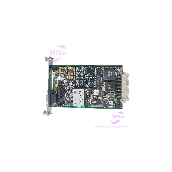
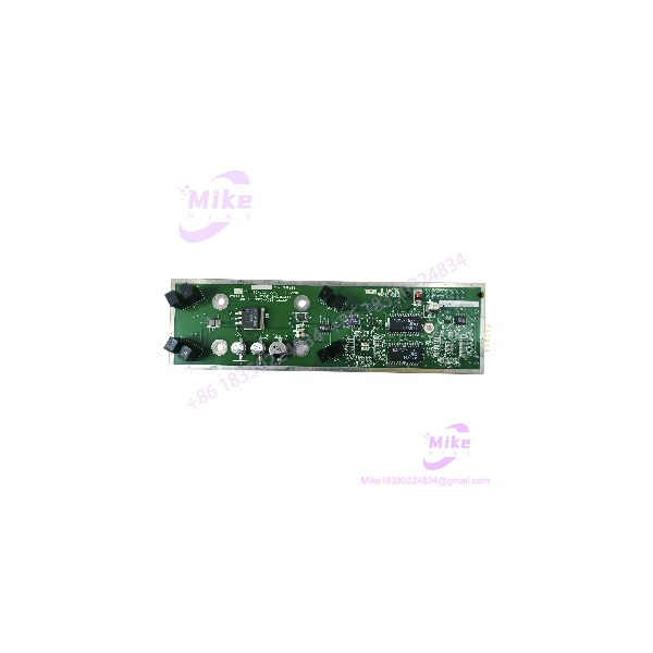
A drive can remain mechanically serviceable while its control electronics become the actual source of downtime. That is where the ETON ET866 becomes relevant: this part is identified as a printed circuit board for drive control, rather than a complete variable-frequency drive or standalone PLC module.
The ET866 is also associated with MPC-ADC6C-010, making the alternate board designation important when searching maintenance records, spare-parts inventories, and legacy drive documentation.
Do not treat the ET866 as a generic plug-in control card. Board-level replacement depends on the exact drive architecture, connector arrangement, board revision, and firmware or configuration associated with the host equipment. A visually similar PCB can still be the wrong replacement.
ET866
Key Technical Specifications
- Manufacturer: ETON
- Part Number: ET866
- Alternate Part Number: MPC-ADC6C-010
- Product Classification: Drive Board
- Board Function: Drive Control
- Construction: Printed circuit board assembly
- Reported Weight: Approximately 0.54 kg / 1.19 lb
- Application Class: Industrial drive-control electronics
- Replacement Type: Board-level replacement component
- Installation: Installed within compatible host drive equipment
- Revision Identification: Verify against the physical PCB before installation
- Connector Configuration: Must be matched against the existing board and host equipment
- Firmware/Configuration: Verify compatibility before commissioning
- Motor Voltage: Not established from reliable documentation reviewed
- Motor Current Rating: Not established from reliable documentation reviewed
- Horsepower/kW Rating: Not established from reliable documentation reviewed
- Input Power: Not established from reliable documentation reviewed
- Fieldbus/Network Interface: Not established from reliable documentation reviewed
The absence of a published drive rating here is deliberate. The ET866 is documented as the drive-control PCB, not as the complete drive specification. Assigning an input voltage or motor power rating to the board itself would create a misleading product listing.
Application Scenarios & Maintenance Pain Points
Legacy Drive Repair
When an older industrial drive has a failed control PCB but the enclosure, power section, motor interface, and mechanical installation remain usable, replacing the board can be more practical than redesigning the entire drive system.
The critical requirement is exact board identification.
Plant Spare-Parts Inventory
The is a useful candidate for legacy-drive spare inventory when the corresponding equipment is still operating in production.
For maintenance departments, recording both and MPC-ADC6C-010 helps avoid a common procurement problem: searching under only one identifier and missing compatible stock.
Drive-Control PCB Failure
A failed control board can present symptoms that initially look like a power-stage, motor, or wiring problem. Before replacing the entire drive, maintenance personnel should isolate the fault at the board and system level.
Obsolete Equipment Support
Legacy industrial hardware often has a much longer operational life than its original commercial sales cycle. A verified replacement can therefore have considerably more maintenance value than its simple “PCB” description suggests.
QA & Live Testing SOP
We treat as a board-level industrial spare, not as a generic electronic card.
Step 1 — Physical identification
- Confirm the PCB marking shows or the applicable alternate designation.
- Record all visible revision markings.
- Compare connector positions and board geometry with the customer’s existing card.
- Check for missing components, cracked PCB material, corrosion, overheated areas, or damaged connectors.
Step 2 — Part-number cross-check
- Match against the equipment documentation.
- Cross-check MPC-ADC6C-010 where applicable.
- Do not rely on appearance alone.
Step 3 — Electrical inspection
We inspect the PCB for obvious shorts, damaged semiconductor packages, burned components, lifted pads, contamination, and connector damage before any powered test.
Step 4 — Functional test
Where the correct host drive and test configuration are available, the board should be evaluated in the corresponding drive architecture rather than connected to an arbitrary power source.
A drive-control PCB should never be powered simply to “see if it works” without confirming the required host system, supply rails, connectors, and protection conditions.
Step 5 — Packaging
After inspection/testing, use ESD-safe packaging and sufficient mechanical protection. Connector pins and exposed board areas should be protected against impact and electrostatic discharge during international transportation.
Field Engineer’s Pitfall Guide
❗ Do not confuse with a complete drive.
The documented product classification is a drive board / printed circuit board / drive control, not a complete inverter or motor controller.
❗ Do not specify motor kW or voltage from the number alone.
Those values belong to the host drive configuration and cannot safely be inferred from the PCB identifier.
❗ Verify the alternate number and physical revision.
is associated with MPC-ADC6C-010, but connector layout, revision markings, firmware, and host-drive compatibility still need to be checked before installation.
❗ Do not substitute a visually similar PCB without documentation.
A drive-control card can contain configuration-dependent electronics that make an apparently identical board unsuitable for a particular chassis or drive revision.
Intent-Driven FAQ
What is ETON ?
ETON is a drive-control printed circuit board / drive board. It is not identified as a complete variable-frequency drive.
What is the alternate part number for ETON ?
The is listed with as an alternate part number.
Is ETON a PLC module?
No. Available technical listings classify it as a drive board / drive-control PCB, not a PLC CPU or conventional PLC I/O module.
Can be used as a universal replacement drive board?
No. Compatibility should be confirmed against the complete drive assembly, PCB revision, connector arrangement, and applicable equipment documentation.
What motor voltage does support?
The board identifier alone does not establish a motor-voltage rating. The applicable voltage must be obtained from the host drive model and technical documentation.
What horsepower or kW rating is ?
No reliable source reviewed establishes a standalone horsepower or kW rating for the PCB. It should not be advertised with an invented motor rating.
How should I verify an replacement before ordering?
Match the existing board’s / -010 marking, revision information, connector arrangement, physical layout, and host-drive model. For high-risk replacement work, a clear photograph of the PCB nameplate and connector side is the safest final verification step.
Procurement Note
For a legacy-drive replacement, specify together with when applicable. The part is documented as a drive-control PCB, and current industrial-part listings continue to categorize it under drive boards.
Before purchase, verify the actual board revision and host-drive compatibility. That check is more important than relying on a generic “ replacement” description.