


Description
Woodward 9905-970 | 18-32 VDC 3.7W Temperature Monitoring Node Quantified Spec
Dynamic Product Introduction
Accurate thermal feedback keeps high-output gas turbines and industrial compressors from stepping over their metallurgical limits during load swings. The Woodward 9905-970 operates as a specialized LinkNet node engineered to aggregate 100-ohm platinum RTD inputs directly from critical bearing and exhaust locations, bypassing the noise degradation common in long analog signal runs. Unlike centralized I/O racks that force massive multi-core cabling bundles across a skid, this distributed module digitizes temperature points close to the source and streams them securely via serial communication links.
Moving past legacy signal-conditioning cards, this LinkNet variant delivers superior channel-to-channel isolation and faster update rates for closed-loop thermal protection schemes. Field maintenance data shows that dropping in this module resolves sporadic open-circuit alarms while maintaining tight measurement linearity under severe ambient temperature shifts.
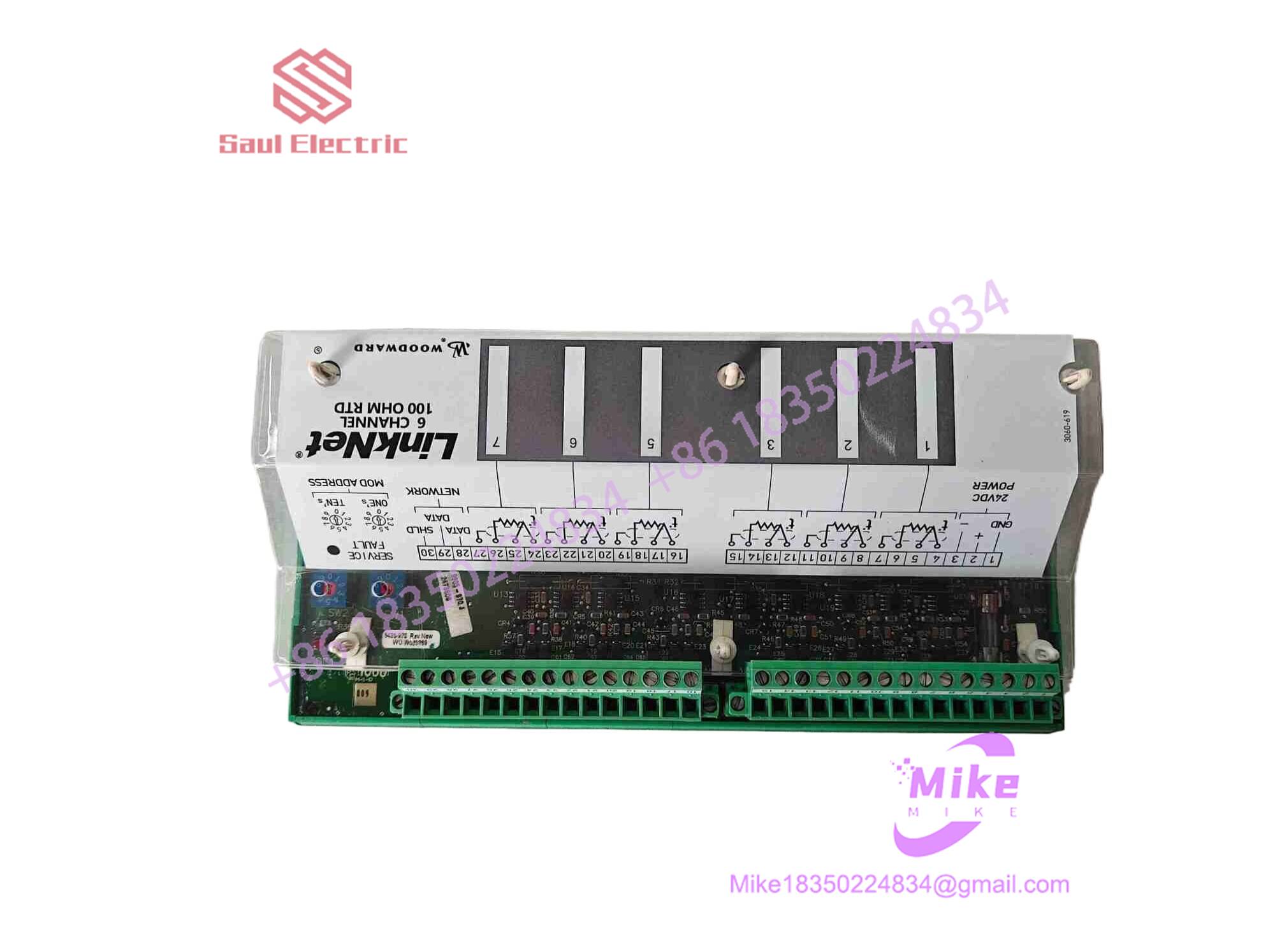
9905-970
Key Technical Specifications
- Input Channels: 6 isolated channels per module
- Sensor Compatibility: 100-ohm Platinum RTD (Alpha = 0.00385 or equivalent standards)
- Supply Voltage: 18 to 32 VDC isolated auxiliary power
- Power Consumption: Approximately 3.7W nominal
- Communication Interface: LinkNet serial protocol bus connecting to main controller
- Conversion Accuracy: High-resolution analog-to-digital conversion optimized for low-level resistance signals
- Operating Temperature Range: -40°C to +70°C industrial ambient tolerance
- Enclosure Type: Modular DIN-rail or rack-mountable field block with pluggable screw terminals
- Weight: ~0.45 kg (1 lb)
- Diagnostics: Front-panel LED status indicators for power, communication health, and channel fault states
Global Sourcing & Live-Test SOP (Transparency Core)
Procuring surplus or pre-owned distributed I/O hardware demands rigorous bench testing to ensure long-term stability in harsh plant environments.
- Inbound Verification: Incoming modules are audited against OEM source documentation, with serial numbers verified to screen out obsolete hardware revisions or unverified clone lots.
- Live Simulation: Technicians mount the unit onto a live LinkNet test bus powered by an authentic Woodward controller rack, terminating each of the six channels with precision decade resistance boxes.
- Diagnostics: Resistance values are swept from 0 to 300 ohms across all channels to validate ADC linearity and verify that temperature conversion tables match factory standards. Modules undergo a 24-hour powered heat run to catch thermal intermittent faults.
- Final Prep: Once communication handshakes and error-handling routines pass inspection, terminal blocks are cleaned, and the unit is sealed in a certified ESD-safe moisture-barrier bag.
The Field Engineer’s Pitfall Guide
❗ Mixing Up 2-Wire, 3-Wire, and 4-Wire RTD Compensations: Terminating a 3-wire RTD incorrectly on a channel mapped for 2-wire loops introduces massive lead-wire resistance errors into the temperature calculation. (I’ve seen plants chase phantom high-bearing-temp alarms for days because a technician ignored the lead compensation jumper settings.) Always verify field wiring diagrams against terminal block assignments.
❗ Grounding Shield Drains at Both Ends: Landing the twisted-pair cable shield at both the module chassis and the sensor housing creates a ground loop susceptible to massive electromagnetic interference from nearby ignition systems or variable frequency drives. Always terminate shields cleanly at a single designated grounding point.
❗ Ignoring LinkNet Baud Rate and Address DIP Switches: Swapping a module without matching the legacy network address or termination jumper configuration will lock the node out of the scanning loop, throwing immediate communication loss faults on the main controller screen.
Intent-Driven FAQ
Will replacing this LinkNet module require reloading the main CPU application logic?
No. The core application logic resides on the central CPU controller. The LinkNet node operates as a smart peripheral device; once configured with the correct network address, it automatically streams its digitized channel data back to the master controller upon power-up.
Can the 9905-970 module be replaced while the turbine is running?
Because LinkNet modules communicate over a shared serial network bus, hot-swapping a powered node can disrupt token-passing and trigger a communication timeout fault on the primary CPU, potentially causing an unwanted trip. It is always safest to de-energize the specific 18–32 VDC loop feed before disconnecting terminal plugs.
What causes a channel to read maximum scale (open circuit) falsely?
A max-scale reading usually indicates a broken sensor wire, a loose terminal screw, or an oxidized contact point on the pluggable connector block. Checking resistance directly at the terminal with a calibrated multimeter will quickly isolate whether the fault lies in the field wiring or the module input channel.
Is this module compatible with copper or nickel RTDs instead of platinum?
The 9905-970 is explicitly engineered and calibrated for 100-ohm platinum RTD curves. Using alternative sensor types like nickel or copper will result in severe non-linear temperature calculation errors unless the main controller’s linearization tables are custom-configured for those specific curves.
What kind of warranty covers surplus 9905-970 units?
Reputable industrial suppliers typically back tested surplus or refurbished automation components with a standard 1-to-2 year replacement warranty, backed by an independent bench test report confirming channel-by-channel resistance accuracy.





