

Description
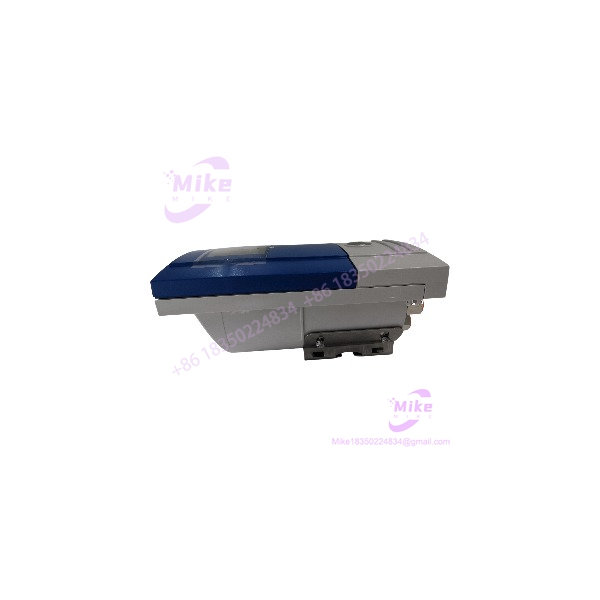
KROHNE OPTISONIC 6300 Ultrasonic Clamp-On Flowmeter for Liquid Measurement
Product Introduction
Cutting a process pipe to install an inline flowmeter can mean production downtime, draining the line, and additional mechanical work. The KROHNE OPTISONIC 6300 provides an alternative: ultrasonic transducers attach to the outside of the pipe and measure liquid flow without direct contact with the process medium.
The system uses ultrasonic transit-time measurement. A sensor rail holds the transducers in position, and the signal converter evaluates the acoustic measurements to determine flow-related values. Depending on configuration, the system can report volume flow, mass flow calculated using configured density, flow velocity, and flow direction.
The OPTISONIC 6300 is intended for permanent industrial installations, including applications where inline instrumentation is difficult to install or maintain. KROHNE offers different sensor sizes and converter configurations, so the correct combination must be selected for the pipe diameter, process temperature, liquid properties, and control-system interface.
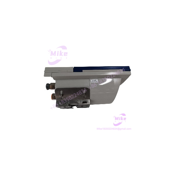
OPTISONIC 6300
Key Technical Specifications
The following specifications describe the OPTISONIC 6300 product family. Exact ratings depend on the installed version and options.
- Manufacturer: KROHNE
- Product family: OPTISONIC 6300
- Product type: Permanent-installation ultrasonic clamp-on flowmeter
- Measurement principle: Ultrasonic transit time
- Measured medium: Liquids
- Sensor arrangement: External clamp-on sensor rail with integrated ultrasonic transducers
- Sensor size range: DN15–DN4000 (½–160 inches), depending on version
- Measurement velocity range: 0.1–20 m/s, depending on configuration and application conditions
- Process temperature: Standard version up to +120 °C; extended-temperature (XT) versions up to +200 °C
- Analog output: 4–20 mA, with HART available on compatible configurations
- Other interfaces: Modbus, Foundation Fieldbus, and Profibus variants are available depending on the ordered configuration
- Installation: External mounting; no pipe cutting required for the clamp-on measurement principle
- Converter options: Wall-mounted or field-mounted signal converter
- Protection options: Sensor and converter protection ratings vary by component and enclosure version; IP68/NEMA 6P options are available for specified configurations
- Diagnostics: Device and process diagnostics, with NAMUR NE 107 support on applicable versions
- Temperature and materials: Sensor rail materials and temperature ratings vary by model and option
Electrical and installation notes
Older OPTISONIC 6300 documentation specifies 100–230 VAC as a standard converter supply, with 24 VAC/DC available as an option on applicable versions. Do not assume the supply requirements of one converter apply to another. Verify the converter nameplate and wiring diagram before connecting power.
The handbook also specifies installation considerations such as adequate straight pipe runs, pipe-wall and liner thickness limits, and suitable acoustic coupling between the sensors and pipe. Measurement accuracy depends on correct installation and process conditions; a published accuracy figure should not be treated as guaranteed for every pipe and liquid.
Application Scenarios & Pain Points
Water and utility flow monitoring
The clamp-on arrangement can be useful for measuring water flow in process and utility piping without introducing wetted sensor components. Confirm that pipe material, diameter, wall thickness, and liquid conditions are supported.
Chemical and process-liquid systems
External installation can avoid cutting into the process line. Before selecting the instrument, verify the liquid’s acoustic properties, gas content, solids content, temperature, and any required hazardous-area certification.
Retrofits on operating plants
Where an inline meter would require extensive piping changes, the OPTISONIC 6300 may reduce mechanical intervention. The actual installation still requires safe access to the pipe, correct sensor positioning, and appropriate signal-cable routing.
Flow monitoring in automation systems
The converter’s supported analog and digital outputs can connect measurement data to compatible PLC, DCS, SCADA, or process-control systems. Confirm the installed I/O module and communication protocol rather than assuming every OPTISONIC 6300 supports every listed interface.
High-temperature liquid measurement
The XT version supports process temperatures up to +200 °C on applicable sensor configurations. Verify the exact sensor rail, coupling arrangement, mounting accessories, and converter limitations before using it in a high-temperature process.
Practical limitation: Clamp-on ultrasonic measurement depends on the quality of the acoustic path through the pipe wall and liquid. Heavy deposits, unsuitable pipe materials, poor coupling, excessive gas, and unfavorable flow conditions can reduce signal quality or measurement reliability.
QA & Live Testing SOP
Use this procedure when inspecting incoming stock or commissioning a replacement instrument. It is a recommended workflow, not a claim that any specific unit has been tested.
1. Verify the complete model identity. Record the converter model, sensor designation, serial numbers, hardware revision, and any option codes. A listing titled only “OPTISONIC 6300” may not describe a complete system.
2. Inventory the assembly. Confirm whether the supply includes the signal converter, sensor rail or rails, transducers, signal cables, mounting hardware, coupling materials, and required accessories.
3. Inspect the sensor assembly. Check rails, transducer housings, cable glands, connectors, and mounting hardware for damage, corrosion, and evidence of improper repair.
4. Inspect the converter. Check the enclosure, display, cable entries, terminals, and nameplate. Verify whether the unit is wall-mounted or field-mounted and whether the enclosure rating suits the installation.
5. Confirm electrical requirements. Read the converter’s nameplate and wiring documentation to determine the correct supply voltage, grounding arrangement, and I/O configuration. Do not energize a unit using assumed ratings.
6. Verify the measurement setup. Confirm pipe diameter, material, wall thickness, liner details, liquid properties, and required measuring range. Use the manufacturer’s setup instructions to select sensor spacing and mounting position.
7. Check the signal path. Inspect sensor cables and connectors. Verify that the converter detects the sensors and reports acceptable acoustic signal quality before relying on flow readings.
8. Test outputs and communications. Check the configured analog output, HART or digital communication interface, and any pulse, frequency, or status outputs installed on the unit. Verify scaling and alarm behavior with the receiving control system.
9. Compare measurements with a reference. Where practical, compare the instrument against a calibrated reference meter or a known process condition. Record the operating flow, signal quality, process conditions, and observed deviation.
10. Document acceptance. Retain the nameplate data, configuration, installation dimensions, test results, diagnostics, and final pass/fail decision.
For used or surplus equipment, request a clear description of the testing performed. A converter that powers up has not necessarily demonstrated accurate flow measurement with its matching sensor assembly.
Field Engineer’s Pitfall Guide
- Ordering only the converter: The OPTISONIC 6300 is a measurement system. Confirm whether the offer includes the required sensor rail or rails, transducers, cables, and mounting accessories.
- Mismatched sensor and converter: Verify that the sensor assembly and signal converter are compatible. A similar product-family name does not prove that components can be mixed.
- Wrong supply voltage: Converter supply options vary. Check the exact nameplate before wiring.
- Incorrect pipe parameters: Entering the wrong outside diameter, wall thickness, liner information, or pipe material can compromise measurement results.
- Poor sensor coupling: Follow the manufacturer’s mounting and coupling procedure. Incorrect sensor spacing or weak acoustic coupling can cause unstable readings or loss of signal.
- Ignoring liquid conditions: Gas bubbles, excessive solids, or unsuitable process conditions can affect acoustic signal quality. Confirm application suitability before purchasing for critical measurement duties.
- Assuming a universal interface: HART, Modbus, Profibus, and Foundation Fieldbus are configuration-dependent options. Check the converter’s installed I/O and communications hardware.
- Overlooking temperature and protection ratings: The sensor, converter, cables, and accessories may have different operating limits. Confirm ratings for the complete installed assembly.
- Treating clamp-on as installation-free: The method avoids cutting the pipe, but still requires correct mounting geometry, adequate straight pipe sections, access, and validation.
- Skipping calibration or reference checks: For custody, billing, safety, or critical process applications, determine the required verification and calibration procedure before commissioning.
Intent-Driven FAQ
Q1: What is the KROHNE OPTISONIC 6300?
It is an ultrasonic clamp-on flowmeter for permanent measurement of liquid flow. External transducers measure through the pipe wall, avoiding the need to cut the pipe for sensor installation.
Q2: Does the OPTISONIC 6300 require process shutdown for installation?
The clamp-on principle generally avoids opening or cutting into the process line. Installation still depends on access, pipe conditions, and site safety procedures.
Q3: What pipe diameters can it measure?
The product family covers approximately DN15 to DN4000 (½ to 160 inches), depending on sensor size and configuration. Verify the exact range for the sensor assembly being purchased.





