

Description
Honeywell FTA-T-14 | 16-Channel Analog Input FTA
Dynamic Product Introduction
A 4-20 mA loop that looks healthy at the transmitter can still arrive at the FSC input with the wrong electrical conditions. That is where the Honeywell FTA-T-14 earns its place in the architecture.
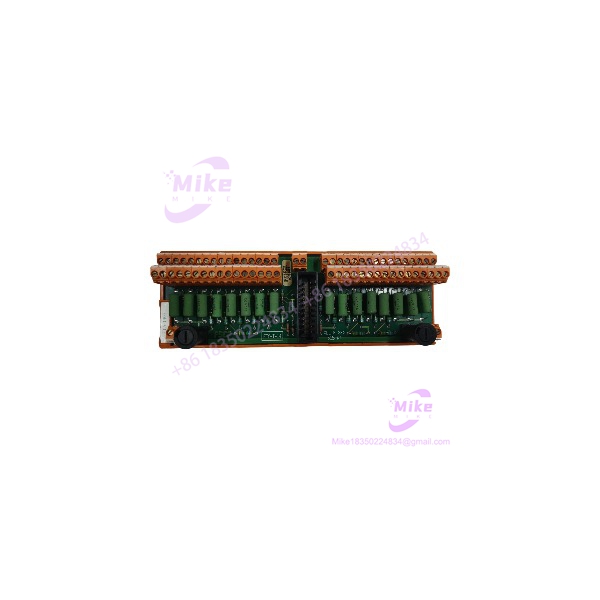
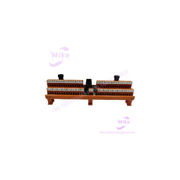
The FTA-T-14 is a dedicated fail-safe analog input Field Termination Assembly for the Honeywell FSC system. It sits between field devices and the 10105/2/1 high-density analog input module, accepting 0(4)-20 mA signals and providing the interface required by the FSC analog-input circuitry. The module has 16 analog channels, arranged as two groups of eight with a common 0 V.
This is not simply a passive terminal strip. The documented architecture uses the FTA-T-14 to convert the incoming current-loop signal into the voltage range required by the 10105/2/1 input module. The published documentation specifies a 250 Ω input resistance and an output signal of approximately 0-4 VDC to the 10105/2/1. That conversion function is why replacing the FTA-T-14 with an ordinary analog termination board is not an equivalent engineering solution.
The FTA-T-14 can also interface active or passive field sensors. In applications using passive transmitters, the associated FTA-T-15 DC/DC converter can provide the required 30 VDC loop supply; Honeywell documentation states that one FTA-T-15 can power up to two assemblies. The exact arrangement depends on whether the field transmitters are active or passive and whether redundant power is required.
FTA-T-14
Key Technical Specifications
- Model:
- Manufacturer: Honeywell
- System: Honeywell Fail-Safe Control (FSC)
- Function: Fail-safe 0(4)-20 mA analog input termination
- Number of Channels: 16
- Channel Arrangement: 2 groups × 8 channels
- Common: Each eight-channel group uses a common 0 V
- Field Signal: 0(4)-20 mA
- Associated FSC Input Module: 10105/2/1
- Input Resistance: 250 Ω ±1%
- Output to 10105/2/1: Approximately 0-4 VDC
- Maximum Loop Current: Less than 120 mA
- Fuse: Slow-acting fuse arrangement; verify exact fuse rating against the applicable hardware revision before replacement
- Field Termination: Screw terminals
- Maximum Field-Wire Size: 2.5 mm² / AWG 14
- Terminal Strip Length: 7 mm recommended strip length
- Terminal Tightening Torque: 0.5 Nm / 0.37 ft-lb
- Mounting: Standard DIN rail
- Hazardous-Area Application: Documented for suitable Class I, Division 2 field applications when the complete installation meets the applicable requirements
- Sensor Types: Active and passive 0(4)-20 mA transmitters, subject to the system configuration
The 250 Ω input resistance is worth highlighting. At 20 mA, that resistance corresponds to roughly 5 V if considered as a simple resistor, but the FTA’s internal conversion architecture produces the specified signal range for the associated 10105/2/1 input. Do not substitute a generic resistor network and assume the FSC will see an equivalent signal.
Global Sourcing & Live-Test SOP
Inbound Verification
For an , the first QC task is confirming that the unit is actually the correct analog-input FTA.
Inspect:
- Exact model marking.
- Honeywell identification and hardware revision.
- Connector type and keying.
- Terminal block condition.
- Fuse locations and fuse condition.
- PCB condition where visible.
- DIN-rail mounting hardware.
- Evidence of field modification or rework.
- Corrosion, contamination, cracked terminal bodies, or damaged connectors.
Do not confuse with the neighboring FSC FTA models. Honeywell’s FTA family contains separate modules for digital inputs, digital outputs, relay outputs, isolated inputs, and analog inputs. The is specifically the fail-safe 0(4)-20 mA analog input model.
Live Simulation
The preferred test rack should contain an authentic FSC configuration using the applicable 10105/2/1 analog input module and the correct system interconnection cable.
Connect the exactly as defined by the approved architecture.
Then simulate representative field signals:
- 0 mA where the application supports the 0-20 mA range.
- 4 mA for the live-zero point of a 4-20 mA transmitter.
- Mid-scale current.
- 20 mA full-scale current.
Verify that the controller-side analog value tracks the injected signal correctly.
For passive transmitters, test the actual power arrangement rather than assuming that the independently provides every required loop-supply function.
Diagnostics
A practical acceptance sequence should include:
- Terminal-to-terminal continuity.
- Conductor isolation checks.
- Fuse inspection.
- Input resistance verification where appropriate.
- Calibrated current injection.
- Controller-side value verification.
- Channel-to-channel mapping confirmation.
- Verification of the common 0 V arrangement.
- Alarm and diagnostic review.
- Repeatability testing at low, mid, and full scale.
Use a calibrated process current source for the analog simulation. A Fluke-class multimeter is useful for voltage, continuity, and basic loop checks, but a proper current source provides much stronger evidence that the is actually processing the signal correctly.
Extended Test
For production-critical replacement stock, run the with representative signal sources for an extended period while monitoring:
- Input current.
- Converted analog voltage.
- Controller-reported process value.
- Fuse condition.
- Channel stability.
- Supply voltage.
- Cabinet temperature.
- Diagnostic status.
The goal is not simply to demonstrate that the unit powers up. The goal is to establish that all 16 channels remain electrically and functionally stable.
Final Prep
Before release:
- Record model and hardware revision.
- Record serial or traceability information where available.
- Photograph the terminal and connector areas.
- Record current-injection test results.
- Identify the test rack configuration.
- Package in ESD-conscious protective material.
- Protect screw terminals and connectors from mechanical impact.
- Attach the QC record to the inventory record.
For safety-system replacement stock, a documented test history is substantially more useful than a generic “tested good” sticker.
The Field Engineer’s Pitfall Guide
❗ Warning 1 — Do not confuse the with an ordinary 4-20 mA terminal board.
The participates in the signal-conversion architecture for the FSC 10105/2/1 input module. Its documented 250 Ω input resistance and conversion to the associated 0-4 VDC input range are part of that system design. I’ve seen generic termination hardware installed during emergency maintenance because the terminal layout looked similar. The loop measured correctly at the transmitter, but the FSC input did not interpret the signal correctly.
❗ Warning 2 — Verify active versus passive transmitter wiring before energizing the loop.
The supports active and passive 0(4)-20 mA sensors, but the power arrangement is different. Honeywell’s documentation describes the FTA-T-15 DC/DC converter as the supply source for passive-transmitter configurations and allows specific redundant arrangements. Do not add an external loop supply simply because the transmitter is labeled “4-20 mA.”
❗ Warning 3 — Do not ignore the two groups of eight channels.
The 16 inputs are arranged as two eight-channel groups with common 0 V. That grouping matters when checking wiring, grounding, and channel mapping. A field engineer can have perfect continuity on every conductor and still create a system problem by moving a channel across the wrong common group.
There is another practical trap: do not assume every 4-20 mA instrument is interchangeable. HART devices, active transmitters, passive transmitters, isolators, and intrinsically safe barriers can impose different loop requirements. Check the complete loop drawing before declaring the compatible.
Intent-Driven FAQ
What is the Honeywell used for?
The is a fail-safe analog input Field Termination Assembly for Honeywell FSC systems. It accepts 0(4)-20 mA field signals and interfaces them with the FSC high-density analog input module 10105/2/1.
How many analog channels does the support?
It supports 16 analog input channels, arranged as two groups of eight channels with a common 0 V.
Is the a 4-20 mA input module?
Not in the same sense as a standalone PLC analog input card. It is a Field Termination Assembly that forms part of the FSC analog-input architecture. The associated 10105/2/1 module performs the system-side analog input processing.





