

Description
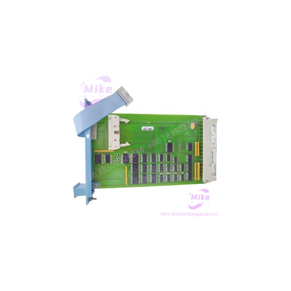
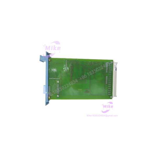
Honeywell FC-IO-0001 | Safety Manager I/O Extender Module
Dynamic Product Introduction
The Honeywell FC-IO-0001 sits at a very different point in the Safety Manager architecture than a normal PLC I/O module. Its job is to extend the controller’s parallel I/O-bus connection into the I/O chassis. Honeywell describes the Safety Manager I/O buses as the communication link between the Control Processors in the controller chassis and the I/O extenders in the I/O chassis.
That makes FC-IO-0001 a system-interface component rather than an I/O channel carrier. The module communicates with the Control Processor through its chassis connection and connects to the horizontal I/O bus through a flat-cable interface. In a redundant I/O chassis, Honeywell specifies two IO-0001 modules, installed in slots 20 and 21, providing the corresponding redundant I/O-bus path.
The distinction matters when sourcing a replacement. A module that merely has the same physical dimensions or connector style is not automatically an acceptable substitute. The I/O bus topology, chassis addressing, key coding, connector configuration, and redundancy arrangement all have to match the Safety Manager installation.
The FC prefix also has a specific Honeywell meaning: Honeywell’s Safety Manager documentation identifies FS products as non-conformal-coated and FC products as conformal-coated. The FC designation therefore carries more information than simply being an alternate catalog number.
FC-IO-0001
Key Technical Specifications
- Manufacturer: Honeywell
- Part Number: FC-IO-0001
- Module Designation: IO-0001
- System: Honeywell Safety Manager
- Function: I/O Extender Module
- Type Numbers: FS-IO-0001 and FC-IO-0001
- Approvals: CE, TÜV, UL, CSA, FM
- Supply Voltage: 5 VDC
- Typical/Specified Module Current: 35 mA
- Maximum Ripple Content: <50 mV peak-to-peak
- Space Requirement: 4 TE, 3 HE
- Equivalent Mechanical Format: 4 HP, 3U
- Module Connector Coding: Holes A5, A7
- Chassis Connector Coding: Large pins A5, A7
- I/O Bus Connection: Flat-cable connection to the horizontal I/O bus
- Chassis Address Selection: CA0, CA1, CA2, CA3 jumpers on the I/O backplane
- Maximum Documented Chassis Address: 9
- Redundant Chassis Application: Two IO-0001 modules can be used in the redundant I/O chassis configuration.
Addressing Note
Do not treat the FC-IO-0001 address as a software-only parameter.
Honeywell specifies chassis address selection through four backplane jumpers: CA0, CA1, CA2, and CA3. The address is established by the jumper configuration on the I/O backplane, with documented addresses from 1 through 9.
That means a replacement module should be checked together with the corresponding backplane and cabling arrangement. Moving a module between chassis positions without verifying the associated addressing configuration is not a sensible commissioning procedure.
Global Sourcing & Live-Test SOP
Inbound Verification
For a Honeywell FC-IO-0001 procurement, begin with physical identification rather than assuming the seller’s model description is sufficient.
Verify:
- FC-IO-0001 marking
- IO-0001 identification
- Version/suffix information where present
- Conformal-coated FC construction
- Connector and key-coding arrangement
- PCB condition
- Chassis connector condition
- Flat-cable interface condition
- Evidence of corrosion, contamination, rework, or damaged solder joints
The supplied listing identifies the item as Honeywell 10100/2/1 (FC-IO-0001) and describes it as new/open-box. That should be treated as the seller’s condition classification rather than proof of factory-sealed stock.
Live Simulation
A meaningful test should reproduce the module’s actual function rather than simply applying 5 VDC to the card.
The preferred procedure is:
- Verify the module against the correct Safety Manager I/O chassis configuration.
- Confirm the appropriate I/O bus cabling.
- Confirm chassis address jumper configuration.
- Power the module from the specified 5 VDC supply.
- Establish communication with the Safety Manager Control Processor.
- Verify recognition of the downstream I/O chassis.
- Confirm expected I/O-bus communication without intermittent faults.
For redundant installations, test both IO-0001 positions and their associated I/O-bus paths independently where the site test procedure permits.
Diagnostics
If the controller does not recognize the I/O chassis, do not immediately condemn the FC-IO-0001.
Check the fault chain systematically:
5 VDC supply → chassis connector → address jumpers → flat cable → I/O extender → I/O-bus termination → downstream I/O chassis.
The FC-IO-0001 itself consumes only 35 mA at 5 VDC, so a large supply-current increase is not an expected characteristic of a healthy module.
Use appropriate electrical test equipment to verify supply voltage and ripple at the module under load. Honeywell specifies less than 50 mV peak-to-peak ripple for the module’s supply requirement.
Final Preparation
Before releasing the module as a production spare, record:
- Exact part number
- Version/suffix
- Conformal-coating condition
- Connector/key-coding condition
- 5 VDC operating test
- I/O-bus communication test result
- Address configuration used during testing
- Redundant/non-redundant test configuration
- Date of functional test
Package the board in ESD-safe material. Protect the chassis connector and flat-cable interface from mechanical impact during transport.
Field Engineer’s Pitfall Guide
❗ Do not confuse FC-IO-0001 with an actual I/O channel module
FC-IO-0001 does not provide the analog or digital field channels itself. It is the I/O Extender Module that provides the interface between the Safety Manager controller-side I/O bus and the I/O chassis.
If a procurement specification calls for an AI, AO, DI, or DO module, FC-IO-0001 is the wrong component.
❗ Do not ignore CA0-CA3 backplane addressing
The I/O extender’s chassis address is established through CA0-CA3 jumpers on the I/O backplane. A replacement that is electrically healthy can still fail system integration if the chassis addressing configuration is incorrect.
One field troubleshooting pattern is particularly familiar: the technician swaps the extender, sees the same communication fault, and assumes the replacement is defective. The real problem is frequently upstream in the backplane addressing or I/O-bus connection.
❗ Do not treat the flat cable as ordinary wiring
The FC-IO-0001 uses the Safety Manager’s dedicated I/O-bus architecture. Honeywell describes the I/O bus as a parallel communication link between the Control Processors and I/O extenders.
A damaged, incorrectly routed, improperly seated, or incorrectly terminated I/O-bus connection can therefore produce symptoms that look like a failed extender.
Intent-Driven FAQ
What is Honeywell FC-IO-0001?
FC-IO-0001 is a Honeywell Safety Manager I/O Extender Module. It provides the interface between the controller-side I/O bus and an I/O chassis; it is not an analog or digital field I/O card.
What voltage does FC-IO-0001 require?
The documented module supply is 5 VDC, with a specified module consumption of 35 mA. Honeywell specifies supply ripple below 50 mV peak-to-peak.
What is the difference between FS-IO-0001 and FC-IO-0001?
Honeywell identifies the FS prefix with non-conformal-coated products and the FC prefix with conformal-coated products. For an existing FC installation, do not assume that an FS version is an equivalent drop-in replacement without checking the applicable system configuration and environmental requirements.
Is FC-IO-0001 used in redundant Safety Manager I/O?
Yes. Honeywell documents a redundant I/O chassis configuration using two IO-0001 modules, installed in slots 20 and 21.
Does FC-IO-0001 use Modbus or another standard field protocol?
Do not classify it as a generic Modbus communication module. Its documented function is as an I/O-bus extender within the Safety Manager architecture, using the dedicated parallel I/O-bus connection between the Control Processor and I/O chassis.
How is the FC-IO-0001 chassis address configured?
The chassis address is configured through CA0, CA1, CA2, and CA3 jumpers on the I/O backplane. Honeywell documents address configurations through address 9.
What should I verify before buying an FC-IO-0001?
Verify the exact FC-IO-0001 identification, version/suffix, FC conformal-coated construction, connector key coding, physical condition, and compatibility with the target Safety Manager I/O chassis. For a used or open-box spare, a live I/O-bus communication test is substantially more useful than a simple continuity check.
The procurement verdict: FC-IO-0001 is a small but system-critical interface component. Its 5 VDC power requirement is straightforward; the difficult part is getting the I/O-bus topology, chassis address, cabling, termination, and redundancy configuration correct. That is where replacement failures tend to originate.





