


Description
HIMA F3501030 982200416 | HIMatrix F35 Safety Controller
Product Introduction
When a compact safety controller has to absorb field I/O, execute safety logic, and communicate with supervisory or distributed equipment without adding a separate I/O rack, the hardware architecture matters more than the marketing label. HIMA F3501030 982200416 is the HIMatrix F35 01 compact safety controller built around that requirement.
The documented F35 architecture combines 24 digital inputs, 8 digital outputs, 8 analog inputs, and two high-speed counters in a metal-enclosed controller. The F35 platform is certified for safety-related applications up to SIL 3 and supports installation in Zone 2 under the applicable equipment conditions.
A key procurement detail is easy to miss: F3501030 / 982200416 is the F35 01 variant associated with the ELOP II Factory programming environment. HIMA documentation lists separate part numbers for the SILworX versions, so replacing a controller based only on the F35 family name is not sufficient. Verify the programming environment, operating-system generation, hardware revision, and existing application before treating the unit as a drop-in replacement.
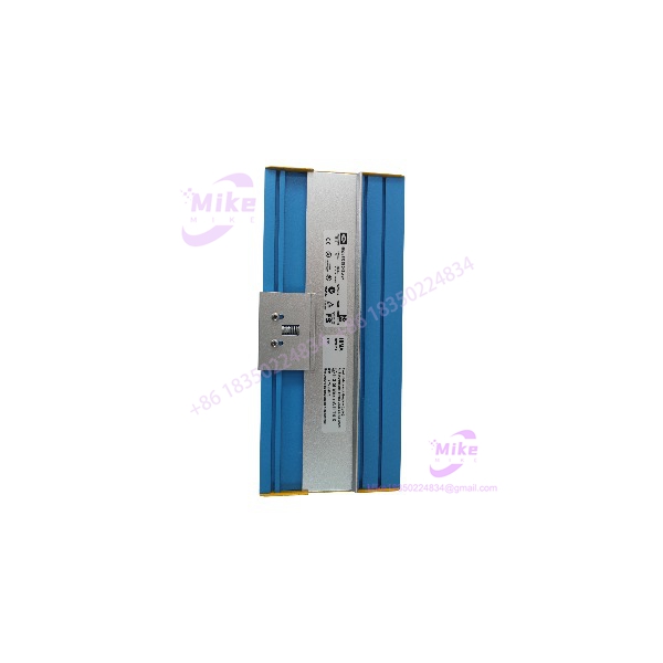
F3501030
Key Technical Specifications
- Model: F35 01 / F3501030
- Part Number: 98 2200416 / 982200416
- Controller Type: HIMatrix compact safety-related controller
- Digital Inputs: 24, non-galvanically isolated
- Digital Input Type: 24 V current-sinking logic, IEC 61131-2 Type 1
- Analog Inputs: 8, unipolar, non-galvanically isolated
- Analog Input Range: 0–10 VDC; 0–20 mA with external shunt
- Analog Resolution: 12 bit
- Digital Outputs: 8, non-galvanically isolated
- Output Capacity: Channels 1–3 and 5–7 up to 0.5 A at 60°C; channels 4 and 8 up to 1 A at 60°C or 2 A at 50°C
- Total Output Current: Maximum 7 A
- Counters: 2 non-isolated counters, 24-bit resolution
- Maximum Counter Frequency: 100 kHz
- Counter Input Voltage: Supports 5 V and 24 V signal levels
- Operating Voltage: 24 VDC, -15% to +20%
- Maximum Current Input: 9 A at maximum load
- Idle Current: Approximately 0.5 A
- Operating Temperature: 0°C to +60°C for the F35 01 variant
- Storage Temperature: -40°C to +85°C
- Protection: IP20
- Temperature Classification: T4 / Zone 2 equipment conditions
- Dimensions: Approximately 257 × 114 × 97 mm
- Weight: Approximately 1.2 kg
- Ethernet: 4 × RJ-45, 10/100Base-T integrated switch
- Ethernet Protocols: safeethernet, Modbus-TCP, OPC, SNTP, TCP-SR; EtherNet/IP support depends on the software environment
- Fieldbus: Optional fieldbus submodules for PROFIBUS, RS485, RS232, RS422, or INTERBUS on FB1/FB2
- FB3: RS485 for Modbus master/slave and ComUserTask
- Safety Certification: Up to SIL 3; documented certification also includes IEC 61508, IEC 61511, EN 954-1 Category 4, PL e, and applicable hazardous-area approvals
The electrical specifications above are taken from the F35 hardware manual rather than generic reseller listings. In particular, the 9 A maximum current figure, 7 A total output limit, 12-bit analog resolution, and 100 kHz counter capability should not be replaced with generic PLC specifications from unrelated F35 variants.
I/O and Communication Architecture
The F35 is more than a conventional CPU module.
Its 24 digital inputs use 24 V current-sinking logic. The inputs are processed as analog measurements internally, allowing configurable thresholds for determining logical HIGH and LOW states. The documented default HIGH threshold is approximately 13 V and the default LOW threshold is approximately 7 V, with safety-related configuration parameters controlling the final thresholds.
The eight analog inputs provide a nominal 0–10 VDC range and can accommodate current measurement using external HIMA shunt adapters. The documented system provides 12-bit resolution, approximately 45 µs sampling time, and a measured-value refresh once per controller cycle.
The eight digital outputs are also integrated into the safety-related controller. Output channels are not all rated identically: channels 1–3 and 5–7 are specified for 0.5 A at 60°C, while channels 4 and 8 can reach 1 A at 60°C or 2 A at 50°C. Overload behavior is handled by switching the affected output off and attempting cyclic reactivation.
The two integrated counters support 24-bit resolution and up to 100 kHz input frequency, with A/B/Z inputs and configurable 5 V or 24 V operation. That makes the counter subsystem useful for pulse, encoder, speed, or position-related safety applications where conventional slow PLC scan-based counting would be inadequate.
On the communications side, the F35 provides four RJ-45 Ethernet ports with an integrated switch and 10/100Base-T operation. The documented protocols include safeethernet for safety-related communication and several non-safety communication services including Modbus-TCP and OPC.
Global Sourcing & Live-Test SOP
For F3501030 982200416, procurement should focus on exact hardware identity rather than simply confirming that the front label says “F35.”
1. Inbound Verification
- Photograph the complete nameplate before unpacking.
- Confirm F35 01 / 982200416 against the purchase order.
- Record serial number, production information, HW revision, and firmware revision.
- Verify that the controller is actually the ELOP II Factory variant.
- Check enclosure condition, terminal connectors, Ethernet sockets, fieldbus interfaces, and mounting hardware.
- Trace available OEM documentation and previous application records where possible.
- Inspect labels and barcodes for inconsistencies or evidence of relabeling.
The HIMA manual specifically shows the type label carrying the product name, part number, production year, hardware revision, firmware revision, operating voltage, and conformity information. Those fields are valuable during anti-counterfeit and compatibility screening.
2. Live Simulation
For a used or surplus F3501030, a proper test rack should reproduce the relevant 24 VDC field conditions rather than simply powering the controller.
Recommended checks include:
- 24 VDC power-up and current-draw observation
- Digital input state verification across representative channels
- Analog input verification using calibrated voltage/current sources
- Digital output switching under controlled loads
- Counter pulse simulation at multiple frequencies
- Ethernet link and port diagnostics
- safeethernet communication where the application requires it
- Modbus communication handshake where configured
- Fieldbus interface verification where optional submodules are installed
- RUN/STOP/FAULT behavior verification
- Diagnostic message and LED verification
Do not treat a successful power-up as a functional acceptance test.
3. Diagnostics and Firmware Record
Record the firmware/operating-system information before changing anything. This is particularly important because the F35 family spans different programming environments and software generations. HIMA’s manual explicitly distinguishes ELOP II Factory and SILworX system variants, and projects created in one environment are not interchangeable with the other.
4. Final Preparation
After testing:
- Save the recorded firmware and hardware revision information.
- Protect all connectors against contamination.
- Use ESD-safe packaging.
- Seal the controller against moisture and mechanical shock.
- Include the recorded serial number in the QC report.
- Preserve the original label and identification markings.
Field Engineer’s Pitfall Guide
❗ Do not assume every F35 with part number 982200416 is interchangeable with a SILworX F35.
HIMA lists separate part numbers for ELOP II Factory and SILworX variants. If an existing application was engineered in ELOP II Factory, verify the software environment before substitution. A physically compatible controller can still be the wrong procurement choice if the engineering tool and firmware lineage do not match.
❗ Do not calculate output loading from the headline “8 digital outputs.”
The eight outputs have different current capabilities. Channels 1–3 and 5–7 are specified at 0.5 A at 60°C, while channels 4 and 8 have higher capacity under specified temperature conditions. The total output current is limited to 7 A. Check actual load distribution rather than treating all eight channels as identical.
❗ Do not overlook the analog-input wiring architecture.
The analog inputs are non-galvanically isolated and support current measurement through external shunt adapters. Grounding, shield termination, signal-source resistance, and shunt selection therefore belong in the commissioning checklist. A nominally correct 4–20 mA loop can still produce unacceptable diagnostic or measurement behavior if the interface configuration is wrong.
Intent-Driven FAQ
Q1. What exactly is HIMA 982200416?
It is the HIMA HIMatrix F35 01 compact safety-related controller, part number 98 2200416 / 982200416. The F35 01 provides 24 digital inputs, 8 digital outputs, 8 analog inputs, and two counters in one compact controller.
Q2. Is 982200416 the same as an F35 SILworX controller?
Not exactly. HIMA’s documentation identifies 982200416 as the F35 01 variant for ELOP II Factory. Separate part numbers are specified for the SILworX variants. Confirm the programming environment before ordering a replacement.
Q3. Can the be used for SIL 3 applications?
The HIMatrix F35 platform is documented for safety-related applications up to SIL 3, with additional certifications including IEC 61508 and IEC 61511. The final safety integrity claim always depends on the complete safety function, engineering, diagnostics, proof-test interval, and application architecture—not simply the controller’s certification.
Q4. What are the ‘s main I/O resources?
The controller provides 24 digital inputs, 8 digital outputs, 8 analog inputs, and two counters. The analog channels provide 12-bit resolution, while the counters support 24-bit resolution and up to 100 kHz input frequency.
Q5. Does the support Ethernet communication?
Yes. The F35 has four RJ-45 10/100Base-T Ethernet interfaces with an integrated switch. The documented communications include safeethernet, Modbus-TCP, OPC, SNTP, and programming/debugging services.
Q6. Does it support PROFIBUS or Modbus?
The F35 architecture supports PROFIBUS and Modbus communication. FB1 and FB2 can accept optional communication submodules, while FB3 provides RS485 for Modbus master/slave and ComUserTask. Exact fieldbus capability depends on the installed submodule and configured software environment.





