

Description
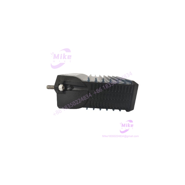
Foxboro FCM2F2 RH914YZ | 2 km Fiber-Optic Fieldbus Module
Dynamic Product Introduction
Long copper fieldbus runs are not always a practical answer in a process plant. High-voltage cable trays, arc welding equipment, rotating machinery, lightning exposure, and large physical separation between the controller cabinet and field devices can make electrical fieldbus links increasingly difficult to manage. The Foxboro FCM2F2 RH914YZ addresses that problem by extending the 200 Series fieldbus through fiber optic cable.
The FCM2F2 is the 2 km version of Foxboro’s FCM family. The related FCM2F4 and FCM2F10 provide nominal maximum baseplate-to-baseplate fiber distances of 4 km and 10 km respectively, making the FCM2F2 appropriate when the remote I/O location is within the 2 km design envelope.
The engineering advantage is not simply distance. Fiber removes the electrical coupling associated with a long copper path. Foxboro specifically describes the fiber connection as unaffected by EMI, RFI, and lightning, which is useful when remote FBM racks have to be placed away from the main control cabinet or near electrically noisy process equipment.
The FCM2F2 is therefore best understood as a fieldbus transport/extender component, not as an independent PLC CPU or conventional Ethernet fiber converter. Its compatibility depends on the Foxboro 200 Series fieldbus architecture, the correct baseplate arrangement, fiber interface, and the corresponding FCM at the remote end.
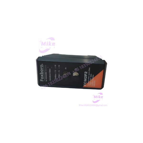
FCM2F2 RH914YZ
Key Technical Specifications
- Manufacturer: Foxboro
- Model: FCM2F2
- Part Number: RH914YZ
- Product Family: Fieldbus Communications Module (FCM)
- System: Foxboro I/A Series / Foxboro Evo
- I/O Platform: Foxboro 200 Series Fieldbus Modules
- Primary Function: Fiber-optic fieldbus extension
- Nominal Maximum Fiber Distance: 2 km / 1.24 miles
- Native Fieldbus Rate: 2 Mbps
- Media: Fiber optic
- Installation: Standard FCM baseplate
- Redundancy: FCMs may be installed in pairs for redundant configurations
- Non-Redundant Operation: A single FCM can be used
- Electrical Isolation Benefit: Fiber path eliminates the normal electrical-noise coupling associated with long copper fieldbus runs
- Related FCM Models: FCM2F4 / RH917JA for 4 km; FCM2F10 / RH916TQ for 10 km
Distance Selection Matters
Do not interpret the “2 km” specification as a casual cable-length recommendation. Foxboro defines these distances as nominal maximum baseplate-to-baseplate fiber-optic cable distances.
For a new installation or migration, verify the complete optical path, fiber type, connectors, routing, and installed FCM pair before assuming that a 2 km nominal rating guarantees a particular plant cable run.
If the application genuinely requires more than the design envelope, the FCM2F4 or FCM2F10 family members are the relevant architectural alternatives—not an arbitrary third-party fiber converter.
Global Sourcing & Live-Test SOP
Inbound Verification
For , identification should begin with the module nameplate and hardware markings.
Verify:
- designation
- RH914YZ part number
- Foxboro identification
- Connector condition
- Fiber-optic interface condition
- Baseplate connector condition
- Housing integrity
- PCB condition
- Signs of cracked optical components or impact damage
- Evidence of previous repair or component replacement
For a surplus module, inspect the optical interface particularly carefully. Fiber hardware can appear cosmetically acceptable while having damaged connectors or internal optical components.
Live Simulation
A meaningful functional test requires more than powering the card.
The preferred test sequence is:
- Install the in the appropriate Foxboro FCM baseplate.
- Connect the corresponding fieldbus infrastructure.
- Establish the fiber connection to the remote FCM/baseplate.
- Verify fieldbus communication at the expected 2 Mbps rate.
- Place representative 200 Series FBM hardware on the remote side.
- Confirm communication between the control-side and remote I/O-side equipment.
- Exercise representative I/O points.
- Monitor for intermittent communication errors during an extended run.
For redundant applications, test the two FCM paths independently and then under the intended redundancy arrangement.
Diagnostics
When a remote FBM installation disappears, troubleshoot the complete path instead of immediately replacing the :
Controller-side fieldbus → → fiber path → remote FCM → remote baseplate → FBM.
Useful isolation steps include:
- Verify the FCM is correctly seated.
- Check fiber connector cleanliness.
- Verify the correct fiber path.
- Confirm the remote FCM is compatible.
- Check the baseplate and fieldbus connections.
- Substitute a known-good fiber path where practical.
- Compare redundant communication paths independently.
A clean electrical measurement on the copper side does not prove that the optical link is healthy.
Final Preparation
Before releasing an as a maintenance spare, record:
- Exact model
- RH914YZ part number
- Hardware revision where available
- Physical condition
- Fiber-interface condition
- Baseplate interface condition
- Successful fieldbus communication test
- Test configuration
- Test date
Protect optical connectors against contamination and impact. Keep protective caps installed whenever the fiber interface is not connected.
Field Engineer’s Pitfall Guide
❗ Do not mistake for a generic Ethernet fiber converter
The is part of the Foxboro 200 Series fieldbus architecture. It is not a general-purpose Ethernet media converter.
That means a standard industrial fiber switch or copper-to-fiber converter cannot simply be substituted because the plant happens to use fiber.
The communication protocol, baseplate interface, timing, and fieldbus architecture are different.
❗ Do not exceed the distance specification because the fiber itself “looks good”
is the 2 km nominal version. Foxboro separately specifies the FCM2F4 for 4 km and FCM2F10 for 10 km.
A common migration mistake is to select the 2 km module because the actual straight-line distance between cabinets is below 2 km, while the installed cable route is significantly longer after tray routing, building penetrations, service loops, and cabinet separation are included.
Measure the actual optical path—not the drawing’s straight-line distance.
❗ Do not overlook redundancy configuration
Foxboro specifies that FCMs can be mounted in pairs for redundancy, while non-redundant configurations require only one FCM.
If the existing control strategy depends on redundant fieldbus communications, replacing one failed module with a single unpaired unit may restore communication but leave the plant without the intended redundancy.
That is a maintenance recovery, not a complete restoration.
Intent-Driven FAQ
What is Foxboro RH914YZ?
is a Foxboro Fieldbus Communications Module used to extend 200 Series fieldbus communications over fiber optic cable. It allows remote FBM I/O to be located closer to the process while maintaining the fieldbus connection to the control system.
What is the maximum distance of ?
Foxboro specifies a nominal maximum baseplate-to-baseplate fiber distance of 2 km (1.24 miles) for .
What is the difference between , FCM2F4, and FCM2F10?
They are different distance versions of the same general FCM architecture:
- up to 2 km
- FCM2F4 / RH917JA: up to 4 km
- FCM2F10 / RH916TQ: up to 10 km
The correct selection depends on the actual baseplate-to-baseplate fiber distance and system design.
Does support redundant operation?
Yes. Foxboro documents FCMs as being installed in pairs for redundancy. A non-redundant installation can use a single FCM.
What type of equipment does connect?
It is intended for the Foxboro 200 Series Fieldbus Module architecture, allowing those fieldbus modules to be remotely mounted near the process.
Why use instead of a long copper fieldbus connection?
The primary reason is plant topology and electrical environment. Fiber provides physical separation between the control and remote I/O locations while avoiding the electrical-noise susceptibility associated with long copper paths. Foxboro specifically identifies EMI, RFI, and lightning immunity as advantages of the fiber link.





