


Description
Foxboro FBM242 | 16-Channel Discrete Output Module
Product Introduction
When a DCS has to switch real field loads, the output module is only half the electrical design. The field supply, load current, termination assembly, fusing, relay architecture, and fail-safe behavior all determine whether the installation is actually suitable.
Foxboro FBM242 is a dedicated 16-channel discrete output module for that job. Each output is externally sourced, allowing the field circuit to use an appropriate external power supply rather than relying on the FBM to provide the load power. Schneider specifies output capability up to 2 A at 60 VDC, while compatible termination assemblies extend the interface to relay-switched 120 VAC, 125 VDC, and 240 VAC applications.
The FBM242 also provides galvanic isolation between output channels and ground, supports digital I/O application processing and ladder logic, and provides configurable fail-safe output behavior. This makes it a discrete control interface rather than merely a collection of 16 transistor switches.
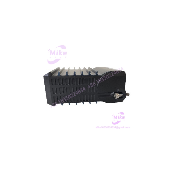
FBM242
Key Technical Specifications
- I/O type: Discrete output
- Number of output channels: 16
- Output architecture: Externally sourced
- Direct DC switching range: 15–60 VDC
- Maximum direct output current: 2 A per channel
- Output isolation: Individual channel isolation
- Field power: Supplied externally
- Application processing: Digital I/O
- Logic support: Ladder Logic
- Fail-safe configuration: Supported
- Fail-safe fallback: Configurable
- Input filtering: Not applicable to the output-only FBM242
- Module Fieldbus: Redundant 2 Mbps
- Fieldbus paths: A/B
- Environment: Class G3 harsh industrial environment
- Termination: Dedicated FBM242 termination assemblies
- Primary application: Discrete actuators, solenoids, contactors, relays, motor-control interfaces, and other field loads
The direct solid-state output specification should not be confused with the ratings of relay-based termination assemblies. The latter can provide switching of substantially higher AC/DC voltages, but the relay TA becomes the component that determines the applicable load rating and isolation architecture.
Output Architecture
The standard FBM242 interface uses an external field power source.
This is an important distinction from an internally powered discrete output card. The FBM provides the switching function while the field supply provides the energy delivered to the load.
For the direct external-source configuration, Schneider specifies operation in the 15–60 VDC range with a maximum of 2 A per output channel. Each output is isolated from the other channels and from ground.
This architecture is useful for loads such as:
- DC solenoid valves
- Interposing relays
- Contactors
- Motor starter control circuits
- Alarm devices
- Actuator interfaces
- Other discrete DC loads
Load characteristics still matter. A nominally 24 VDC solenoid, for example, may have a significantly different inrush and turn-off behavior from a relay coil or electronic input. Protection against inductive transients should therefore be evaluated at the field-load level.
Termination Assembly Options
The TA is a major part of the system.
Schneider documentation identifies termination assemblies for several output architectures, including externally sourced solid-state switching and relay-based outputs.
Representative configurations include:
- Direct externally sourced DC output: Up to 60 VDC / 2 A per channel
- SPDT/Form C relay output: Up to 250 VAC / 5 A maximum under specified conditions
- Relay output for DC loads: Up to 125 VDC, with current limits dependent on resistive or inductive load
- Relay output with power distribution: Provides field-power distribution and group-level current limitations
The current documentation lists termination assemblies such as:
- RH923LL — SPDT/Form C relay configuration
- RH916YY — SPDT/Form C relay configuration
- RH916YZ — relay output with power distribution
Older installations may carry superseded P-series TA numbers such as P0923LL, P0916YY, P0916NG, P0916YZ, or P0916JZ. Do not substitute one based solely on physical appearance; verify the exact electrical configuration and revision.
Control Logic and Fail-Safe Operation
interfaces the control processor’s discrete output commands with the field.
The module executes a digital I/O application program and supports Ladder Logic. It also provides configurable fail-safe functionality, allowing the control strategy to define what happens when communication or other defined fault conditions occur.
For critical outputs, the fallback state must be selected based on the process hazard analysis.
A valve that should de-energize on loss of control is not configured the same way as an alarm horn that should remain energized. The hardware provides the output mechanism; the actual safe state is a system-engineering decision involving the logic configuration, field device, TA, and final element.
Fieldbus Architecture
The is part of the Foxboro I/A Series 200 Fieldbus I/O architecture.
The module communicates with the control system through a redundant 2 Mbps Fieldbus. The redundant communication architecture is independent of the external field-power circuit.
That distinction matters during troubleshooting. A healthy Fieldbus indication does not prove that an output has correct field voltage, correct TA wiring, adequate load power, or a functional final device.
A complete diagnostic sequence should therefore separate:
- DCS output command
- FBM diagnostic state
- Fieldbus communication
- FBM output switching
- TA operation
- External field supply
- Field wiring
- Final load response
Global Sourcing & Live-Test SOP
For used or refurbished hardware, procurement acceptance should test the complete output path rather than simply applying power.
1. Inbound Verification
- Confirm the front label identifies .
- Record serial number and hardware revision.
- Inspect the enclosure for cracking, contamination, corrosion, or heat damage.
- Inspect the Fieldbus connector and baseplate interface.
- Verify the exact TA type required by the customer’s installation.
- Confirm whether the requirement is solid-state DC switching or relay-based AC/DC switching.
- Preserve available OEM documentation and serial-number traceability.





