


Description
Foxboro FBM237 | 8-Channel 0–20 mA Output Module
Product Introduction
When a DCS output card controls a final control element, redundancy is not simply about having a spare module on the shelf. The output architecture has to maintain the field signal when one FBM fails. Foxboro FBM237 addresses this requirement with eight isolated analog output channels and a dedicated redundant operating architecture.
The FBM237 can operate as a standalone module or as a redundant pair. In redundant service, both modules receive the same output writes, while the associated AOUTR control block manages initialization and output handling. If a module failure is detected, its affected output is driven to 0 mA while the healthy module continues supplying the commanded current.
This makes FBM237 particularly relevant to continuous-process applications where an unexpected loss of a control output can create a much larger process problem than the cost of the spare I/O hardware itself.
The module is also electrically compatible with standard HART signals, allowing the analog output loop to coexist with HART communication between a compatible field device and handheld communicator.
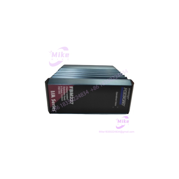
FBM237FBM237
Key Technical Specifications
- I/O type: Analog output
- Number of channels: 8
- Nominal output: 0–20 mA DC
- Output range: 0–20.4 mA DC
- Output accuracy: ±0.05% of span between 0.1 and 20 mA
- Temperature coefficient: ±50 ppm/°C
- Resolution: 13 bits
- Maximum output load: 750 Ω
- Maximum output processing delay: 30 ms
- Compliance voltage: 18 VDC at 20.4 mA output
- Channel isolation: Galvanically isolated channel-to-channel and channel-to-ground
- Fieldbus: Redundant 2 Mbps module Fieldbus
- Power supply: 24 VDC, +5% / -10%
- Maximum module consumption: 7 W
- Maximum heat dissipation: 5 W
- Operating temperature: -20 to +70°C (-4 to +158°F)
- Storage temperature: -40 to +70°C (-40 to +158°F)
- Relative humidity: 5–95%, noncondensing
- Vibration: 0.75 g, 5–500 Hz
- Environmental rating: Class G3 harsh environment
- Approximate module weight: 185 g
- Module dimensions: 102 mm H × 45 mm W × 104 mm D
- Current module part number: RH914XS
- Redundant adapter: RH916QD
Schneider specifies 600 VAC for one-minute withstand testing between channels and ground or between channels. This is an isolation test rating, not a permissible continuous field operating voltage. The published safety limitation prohibits connection to circuits above 30 VAC or 60 VDC.
Redundant Output Architecture
FBM237 redundancy operates at the FBM level.
A redundant pair uses two FBM237 modules connected through a common termination assembly and the appropriate redundant adapter. The modules must occupy adjacent odd/even baseplate positions, such as positions 1–2, 3–4, 5–6, or 7–8.
The AOUTR control block sends identical output writes to both modules during each execution cycle. This continuously exercises the Fieldbus communication path and output circuitry rather than leaving the standby module completely idle.
When a detectable module failure occurs, the failed side is driven to 0 mA and the healthy module maintains the required output.
For fail-safe configuration, Schneider specifies 0 mA as the Analog Output Fail-Safe Fallback Data. This removes the failed channel from service and reduces the possibility of a fail-high output condition.
Termination Assemblies and Field Wiring
The uses DIN-rail-mounted termination assemblies. The current specification identifies two principal TA options:
- RH916YE — 8-channel 0–20 mA termination assembly
- RH917QZ — 8-channel 0–20 mA termination assembly with output bypass jacks
The RH917QZ configuration is worth attention when maintenance continuity matters. Its bypass jacks can accept a bypass plug from the I/A Series Output Bypass Station or another external 20 mA source, allowing field output maintenance procedures to be designed around controlled bypass operation.
Termination cables are available up to 30 m (98 ft) and use either polyurethane/PVC or LSZH construction. The module-side connection is a 25-pin male D-subminiature interface.
For 100 Series modernization projects, Schneider states that can reuse appropriate FBM37 termination assemblies, or field wiring can be transitioned through a Termination Assembly Adapter. This makes the module relevant to a structured migration strategy rather than requiring every legacy field termination to be redesigned from scratch.
Global Sourcing & Live-Test SOP
For procurement of a used, surplus, or refurbished , the following verification sequence should be treated as the minimum technical acceptance procedure.
1. Inbound Verification
- Confirm the front label reads .
- Verify module identification against the expected RH914XS hardware designation.
- Photograph the serial number, date code, revision markings, and connector condition.
- Check the enclosure for cracks, deformation, corrosion, contamination, or evidence of overheating.
- Verify the Fieldbus and baseplate connectors are not bent, oxidized, or mechanically damaged.
- Trace OEM paperwork where available.
- Record the exact hardware revision before quoting compatibility.
2. Live Simulation
Use a compatible Foxboro 200 Series test rack and approved termination hardware.
- Power the module using the specified 24 VDC supply.
- Verify module startup and LED status.
- Establish redundant 2 Mbps Fieldbus communication.
- Exercise all eight output channels individually.
- Command representative 4 mA, 12 mA, and 20 mA points.
- Measure actual loop current using a calibrated Fluke multimeter or equivalent precision current measurement equipment.
- Verify output linearity across the operating range.
- Confirm the connected load remains within the 750 Ω maximum.
3. Redundancy Diagnostics
For a redundant pair:
- Confirm both modules receive identical output commands.
- Verify AOUTR control behavior.
- Simulate an appropriate module-side fault according to the approved test procedure.
- Confirm the failed side transitions toward the configured 0 mA fallback.
- Verify the healthy module maintains the commanded field output.
- Confirm Fieldbus path A/B communication behavior.
- Verify the redundant adapter and common TA wiring.
4. Final Preparation
- Record hardware revision and firmware information where available.
- Preserve the original label and serial-number traceability.
- Perform ESD-safe packaging.
- Protect D-sub and backplane connectors from mechanical impact.
- Include the tested configuration and measured output results with the shipment documentation.
Do not describe an as “tested” merely because power was applied. A meaningful acceptance test should exercise the analog outputs under representative load and, when sold as redundant hardware, verify the redundancy architecture separately.





