


Description
Foxboro FBM219 | 24DI 8DO Discrete I/O Module
Product Introduction
When an old Foxboro installation needs both discrete monitoring and discrete control from one I/O position, the FBM219 is the relevant 200 Series hardware—not the FBM217. Its architecture combines 24 discrete input channels with 8 discrete output channels, with the associated termination assembly determining the field voltage and output capability. Schneider’s current PSS 41H-2S219 identifies FBM219 as the Discrete I/O Interface Module.
The FBM219 was also designed as a migration path from selected 100 Series main/expansion combinations. Schneider’s upgrade documentation maps 100 Series FBM07A/B or FBM08 installations with specified expansion modules to FBM219, providing 24-channel voltage-monitor functionality plus 8-channel discrete output capability.
That makes the FBM219 particularly useful when an existing control strategy needs to preserve established field wiring and discrete logic while moving the I/O architecture into the 200 Series.
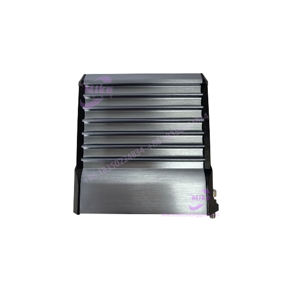
FBM219
Key Technical Specifications
- Model:
- Product Type: Discrete I/O Interface Module
- Discrete Inputs: 24
- Discrete Outputs: 8
- Isolation: Group-isolated I/O
- Input Types: Voltage monitoring or contact-sense configurations depending on termination assembly
- Supported Input Voltage Classes: 15–60VDC, 120VAC/125VDC, or 240VAC, depending on TA
- Output Types: Discrete switching outputs with termination-assembly-dependent voltage/current ratings
- Maximum Output Capability: Up to 30VDC at 0.25A, 30VDC at 5A, 125VDC at 0.6A, 120VAC at 5A, or 240VAC at 5A, depending on the installed TA
- Fieldbus: Communicates with the associated FCM/FCP through the module Fieldbus
- Logic: Discrete I/O and Ladder Logic execution
- Configurable Functions: Input filter, fail-safe configuration, fail-safe fallback, sustained or momentary outputs
- Environmental Design: Suitable for ISA S71.04 Class G3 environments when properly installed
- Current Schneider Specification: PSS 41H-2S219
- Historical Foxboro Part Number: P0916RH
The output ratings are not universal properties of the electronics alone. They depend on the termination assembly. Schneider specifically describes TAs with current limiting, fusing, relays, or relay outputs and internal/external power arrangements.
Termination Assembly Compatibility
This is the part that needs attention when sourcing surplus hardware.
The historical Foxboro parts documentation identifies P0916RH as the module and lists multiple termination assemblies for different field-signal configurations.
Examples include:
- P0917LE: 24 inputs, 15–30VDC switch; 8 outputs, 15–60VDC at 0.25A
- P0917LH: 24 inputs, 24VDC contact/current-limited; 8 outputs, 15–60VDC at 0.25A
- P0917LL: 24 inputs, 120VAC/125VDC switch; 8 outputs up to 125VDC or 120VAC, depending on load
- P0917LP: 120VAC/125VDC input configuration with externally supplied excitation/power arrangement
Other termination assemblies cover additional input/output voltage combinations. The correct TA therefore has to be selected from the actual field circuit design—not simply from the label.
Important: P0916PS
P0916PS should not be advertised as an termination assembly.
Schneider’s certification documentation identifies P0916PS/P0916PT/RH916YA with FBM217, for 32-channel 120VAC/125VDC switch input service.
So if the physical item in the supplied listing is marked P0916PS, the technically correct product description is an FBM217 termination assembly, not an module.
This distinction is especially important for B2B procurement because a buyer matching only the Foxboro family number can easily receive the wrong field interface.
Field I/O Architecture
The separates the field interface problem from the basic I/O processing.
The electronics module provides the discrete I/O processing, while the termination assembly handles the physical field-signal requirements. Depending on the selected TA, the installation can accommodate lower-voltage DC signals or higher-voltage AC/DC circuits.
The module supports configurable input filtering and output behavior. Fail-safe and fallback functions are available for applications where a loss of communication or defined module condition needs to drive outputs to predetermined states rather than leaving the process behavior ambiguous.
For an existing plant, that distinction matters: replacing the without confirming the TA can produce a physically compatible module with an electrically incompatible field interface.
Migration Compatibility
The has a documented role in 100 Series migration.
Schneider’s 100 Series upgrade documentation maps:
- FBM07A/FBM07B + selected expansion FBMs →
- FBM08 + selected expansion FBMs →
The documented function is a 24-channel voltage-monitor interface plus 8-channel discrete output, external-source, group-isolated configuration for these migration paths.
This is useful when planning an I/O migration because the correct replacement is determined by the original main/expansion architecture and field termination arrangement, not simply by channel count.
Global Sourcing & Live-Test SOP
For a used or surplus , identification should be completed before any functional test.
1. Inbound Verification
- Photograph the complete module label.
- Record the Foxboro part number and serial number.
- Verify whether the unit is the electronics module or only a termination assembly.
- Confirm the associated TA part number.
- Inspect the Fieldbus connector and baseplate interface.
- Check for damaged housings, corrosion, contamination, or evidence of unauthorized repair.
- Match the hardware identity against procurement documentation.
2. Live Simulation
A controlled Foxboro-compatible test rack should be used where available.
Verify:
- Module power-up
- Fieldbus communication
- All 24 discrete input channels
- All 8 discrete output channels
- Input filtering
- Contact-sense behavior where applicable
- Voltage-monitor behavior where applicable
- Output switching
- Fail-safe behavior
- Fallback configuration
- Sustained/momentary output behavior
- Ladder-logic execution where the test configuration supports it
For voltage and continuity verification, a calibrated multimeter or suitable industrial test instrument should be used. High-voltage TA configurations require the appropriate controlled test equipment and safety procedures.
3. Diagnostics
Record:
- Firmware revision
- Module identity
- Diagnostic state
- Fieldbus status
- Input-channel status
- Output-channel status
- Any stored or active fault indication
Firmware should be documented rather than assumed from the module’s external appearance.
4. Final Preparation
For shipment:
- ESD-safe handling
- Connector protection
- Anti-static packaging
- Moisture protection
- Serial-number photographs
- Hardware-condition photographs
- Test report only when the stated tests were actually performed
Do not advertise a used as “fully tested” unless the test scope is documented.
Field Engineer’s Pitfall Guide
❗ Do not substitute FBM217 for .
They are adjacent members of the Foxboro 200 Series family, but their I/O architecture is different. FBM217 is a 32-channel discrete-input module; provides 24 inputs plus 8 outputs. Schneider’s current documentation treats them as separate product specifications.
❗ Do not use P0916PS as proof that the hardware is .
P0916PS is associated with FBM217’s 120VAC/125VDC termination arrangement. A seller listing ” ” should therefore be checked carefully before purchase.
❗ Do not select the TA from the module number alone.
The can support substantially different field voltage and output-current configurations depending on the termination assembly. Verify the actual field circuit and TA part number before installation.
Intent-Driven FAQ
Q: What is the Foxboro ?
A: The is an I/A Series 200 Discrete I/O Interface Module with 24 discrete inputs and 8 discrete outputs.
Q: What is the Foxboro part number for ?
A: Historical Foxboro documentation identifies P0916RH as the module part number. Current Schneider documentation identifies the product through the specification and current PSS 41H-2S219 documentation.
Q: Is group isolated?
A: Yes. Schneider specifies the I/O as group isolated.
Q: How many inputs and outputs does have?
A: It has 24 discrete inputs and 8 discrete outputs.
Q: Can handle 120VAC or 240VAC field signals?
A: Yes, with the appropriate termination assembly. The TA determines the supported field-voltage and output-current configuration. Schneider lists 120VAC/125VDC and 240VAC options in addition to lower-voltage DC configurations.





