


Description
Foxboro FBM201D | 8-Channel 0–10 VDC Analog Input
Product Introduction
The important distinction is the final letter.
FBM201D is the 0–10 VDC member of the FBM201 family. The standard FBM201 is a 0–20 mA input, FBM201b handles 0–100 mV, FBM201c handles 0–5 VDC, while FBM201d is specifically designed for 0–10 VDC analog signals. These variants should not be treated as interchangeable simply because the hardware belongs to the same FBM family.
The FBM201D provides eight isolated and independent analog input channels. Each channel uses a high-resolution Sigma-Delta conversion architecture, with the analog input application supporting configurable conversion/integration behavior and rate-of-change limits. Schneider’s documentation specifies ±0.03% of span analog accuracy, including linearity, with a ±50 ppm/°C accuracy temperature coefficient.
For an existing Foxboro I/A Series installation, FBM201D is therefore a specialized voltage-input interface rather than a generic analog card. The field signal passes through the appropriate termination assembly and cable to the FBM, while the module communicates with its associated FCM or FCP over the redundant 2 Mbps module Fieldbus.
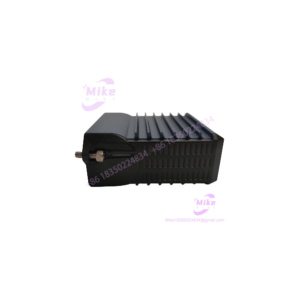
FBM201D
Key Technical Specifications
- Model: FBM201D / FBM201d
- Product type: Analog Input Interface Module
- System: Foxboro I/A Series 200
- Number of channels: 8
- Channel architecture: Isolated and independent
- Input signal: 0–10 VDC
- Input impedance: 10 MΩ nominal
- Analog accuracy, including linearity: ±0.03% of span
- Accuracy temperature coefficient: ±50 ppm/°C
- A/D conversion: Sigma-Delta conversion per channel
- Integration period: Software configurable
- Conversion time: Software configurable
- Update period: 25 ms
- Communication: Redundant 2 Mbps module Fieldbus
- Associated controller/interface: FCM or FCP
- Input isolation: Galvanic isolation between channels and ground
- Isolation withstand: 600 VAC for one minute
- Operating temperature: -40 to +70°C
- Relative humidity: 5–95%, noncondensing
- Altitude: -300 to +12,000 m
- Maximum power consumption: 7 W
- Approximate dimensions: 10.4 × 4.5 × 11.4 cm
- Approximate module weight: 0.284 kg
The 0–10 VDC input range and 10 MΩ input impedance are specifically associated with the FBM201d variant rather than the standard current-input FBM201.
Input Architecture
The FBM201D has eight independent analog voltage inputs.
Each channel is designed to receive a 0–10 VDC process or instrumentation signal. The high input impedance of approximately 10 MΩ minimizes loading of the connected voltage source, which is particularly relevant when interfacing instrumentation outputs that have limited source-drive capability.
The FBM201 family uses separate variants for different analog signal ranges:
- FBM201 — 0–20 mA DC
- FBM201b — 0–100 mV DC
- FBM201c — 0–5 V DC
- — 0–10 V DC
That suffix is therefore an electrical specification, not merely a catalog revision.
Termination Assembly
For the , Schneider’s current PSS identifies RH922ZP as the corresponding compression-terminal termination assembly. A ring-lug termination option is identified as P0926SQ.
The field wiring architecture is:
0–10 VDC field device → termination assembly → termination cable → → redundant 2 Mbps Fieldbus → FCM/FCP
The termination assemblies are electrically passive. The removable termination cable connects the DIN-rail termination assembly to the FBM installed on its baseplate.
This is worth checking during replacement. A physically compatible does not automatically mean that the existing field termination arrangement is correct.
Signal Conversion and Performance
The uses Sigma-Delta conversion for its analog channels. The I/A Series software can configure the analog conversion time, allowing the system to balance response time and measurement stability.
Documented conversion choices for the FBM201 family include:
- 50 ms
- 100 ms
- 200 ms
- 500 ms
- 1000 ms
The associated update period is 25 ms, with 15-bit resolution documented for these conversion settings.
For a process loop where the signal changes relatively slowly, a longer integration/conversion period can provide useful filtering behavior. For faster control applications, the shorter conversion settings reduce measurement latency.
Global Sourcing & Live-Test SOP
Inbound Verification
Before accepting an into stock, verify:
- Exact model marking: / FBM201d
- OEM label
- Serial number
- Hardware revision
- Connector condition
- Baseplate interface
- Evidence of corrosion or contamination
- Correct termination-assembly compatibility
- Packaging and ESD protection
Do not accept an or FBM201C as an simply because the front-panel design appears identical.
Live Simulation
For a functional test, use a calibrated voltage source capable of accurately generating the 0–10 VDC range.
Recommended channel verification:
- 0 V
- 1 V
- 2.5 V
- 5 V
- 7.5 V
- 10 V
Check all eight channels individually.
The test should also verify:
- Correct channel scaling
- Stable readings
- Conversion response
- Diagnostic status
- Fieldbus communication
- Redundant Fieldbus path
- Channel isolation where practical
A calibrated Fluke-class voltage source or equivalent instrumentation can be used for the analog simulation. The purpose is to verify the complete signal path rather than simply confirming that the module powers up.
Diagnostics
Check:
- Operational-status indicators
- Fieldbus communication
- Analog channel values
- Configuration status
- Termination connections
- Input polarity
- Channel-to-channel behavior
- Redundant communication path
- Abnormal diagnostic indications
A power-up test alone is not sufficient evidence that an analog input module is operational.
Final Preparation
Before shipment or installation:
- Record serial number
- Record hardware revision
- Record tested input range
- Record termination configuration
- Photograph connectors and identification labels
- Use ESD-safe packaging
- Protect the module connector
- Include test documentation when available
Do not describe a used or surplus as factory tested unless that status can actually be substantiated.
Field Engineer’s Pitfall Guide
❗ Do not substitute FBM201C for .
Both are voltage-input modules, but FBM201C is designed for 0–5 VDC while is designed for 0–10 VDC. A 10 V process signal requires the correct range.
❗ Check the termination assembly before swapping the module.
The documented compression-terminal assembly is RH922ZP, while P0926SQ is identified for ring-lug termination. The termination hardware should be verified against the installed cabinet configuration before commissioning.
❗ Do not confuse input range with transmitter output capability.
The is a voltage-input module. A field instrument providing 4–20 mA requires the appropriate current-input FBM architecture, not . Conversely, a 0–10 V signal should not be forced through a current-input simply because both products belong to the same family.
Migration and Replacement Considerations
The belongs to the I/A Series 200 family. Schneider’s documentation identifies the /b/c/d family under PSS 41H-2S201, while the earlier PSS 21H-2Z1 documentation has been superseded by later documentation.
For legacy-system migration, the important compatibility points are:
- Exact voltage range
- Channel configuration
- Termination assembly
- Termination cable
- Baseplate
- FCM/FCP compatibility
- Application configuration
- Fieldbus architecture
- DCS scaling
The should therefore be treated as an 8-channel 0–10 VDC interface, not as a generic replacement for every -family module.





