


Description
Foxboro FBM14 | Contact/DC I/O Expansion Module
Product Introduction
The Foxboro FBM14 is not a standalone Fieldbus interface. It is the Contact/DC Input/Output Expansion Interface Module designed to operate with an expandable main FBM, most notably the FBM09. The expansion module adds eight discrete input channels and eight discrete output channels while relying on the supporting main module for Fieldbus communication and application execution.
That architectural point is easy to miss during procurement. The FBM14 does not independently connect to the redundant Fieldbus; it communicates through its associated expandable main module. Foxboro’s original PSS specifies that one main module can support a single expansion module.
On the input side, the FBM14 provides eight independent channels configured collectively for either contact sensing or DC voltage monitoring. Contact sensing uses a 24 VDC ±10% open-circuit voltage with a maximum short-circuit current of 2.5 mA. For voltage-monitor applications, the documented ON-state range is 15–130 VDC and the OFF-state range is 0–5 VDC.
The eight output channels can be configured for DC switching using either an external source or the module’s internal source. External-source switching supports up to 60 VDC and 0.5 A per channel, while the internal-source configuration provides approximately 11 VDC no-load with a nominal 660 Ω source resistance.
For existing I/A Series installations, FBM14 remains relevant primarily as a maintenance and lifecycle-management component. Schneider Electric’s current mature I/A Series documentation still identifies the FBM14 under PSS 21H-2C7 B4 alongside the FBM09 main module.
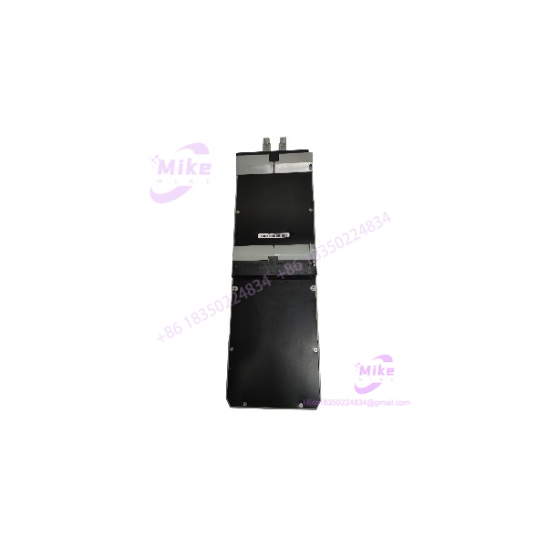
FBM14
Key Technical Specifications
- Model:
- Product type: Contact/DC Input/Output Expansion Interface Module
- System: Foxboro I/A Series
- Architecture: 100 Series Fieldbus Module
- Input capacity: 8 independent digital channels
- Output capacity: 8 independent digital channels
- Input configuration:
- Contact sensing
- DC voltage monitoring
- Input filter time: 4, 8, 16, or 32 ms
- Contact-sensor open-circuit voltage: 24 VDC ±10%
- Contact-sensor short-circuit current: 2.5 mA maximum
- Contact ON-state resistance: 1 kΩ maximum
- Contact OFF-state resistance: 100 kΩ minimum
- Voltage-monitor ON-state: 15–130 VDC
- Voltage-monitor OFF-state: 0–5 VDC
- Voltage-monitor current: 2.2 mA typical at 5–130 VDC
- External-source output voltage: 60 VDC maximum
- External-source load current: 0.5 A maximum
- External-source ON-state voltage drop: 0.5 V typical at 0.5 A
- External-source current limit: 0.75 A typical
- External-source OFF leakage: <100 µA typical, 1.0 mA maximum
- Internal-source output voltage: 11 VDC ±2 VDC no-load
- Internal-source output resistance: 660 Ω nominal
- Power input specification: 26–42 VDC redundant system supply
- Power consumption: 11 W maximum when main module and expansion module are used together
- Heat dissipation: 18 W maximum with main + expansion configuration
- Isolation withstand: 1250 VAC for one minute across specified input/output/ground isolation points
- Communication: Via redundant Fieldbus through the main FBM
- Termination: 32 screw-clamp terminals or 34-pin connector depending on termination assembly
- Operating temperature: 0 to 60°C
- Storage temperature: -40 to 70°C
- Relative humidity: 5–95%, noncondensing
- Contamination rating: ISA S71.04 Class G3
- Approximate mass: 1 kg / 2.2 lb
These specifications are taken from the Foxboro/Schneider PSS for the FBM09/ pair.
Configuration and System Architecture
The should be evaluated together with the main module rather than as an isolated PLC I/O card.
The supported architecture is:
FBM09 main module → expansion module → field I/O
The FBM09 independently communicates with the redundant Fieldbus and executes the applicable digital I/O or ladder-logic application. The receives its system-level communication through that expandable main module.
The input configuration can be used for:
- Contact sensing
- DC voltage monitoring
Its output configuration can be used for:
- External-source DC switching
- Internal-source DC switching
The PSS identifies suffix configurations 14A/14B for voltage-monitor input applications and 14C/14D for contact-sensing applications. External-source output switching is associated with 14A/14C, while internal-source output switching is associated with 14B/14D.
Global Sourcing & Live-Test SOP
Inbound Verification
For an procurement, verify the exact front-panel designation, manufacturer markings, termination arrangement, revision information, and serial number before accepting the unit into inventory.
For older I/A Series hardware, documentation tracing matters. Record the original part number, revision, serial information, packaging condition, and any available OEM paperwork. Do not substitute a visually similar FBM simply because the connector arrangement appears compatible.
If the sourcing record identifies CM400YQ, secondary Foxboro inventory documentation associates that part number with . The primary technical PSS, however, should remain the authority for electrical specifications.
Live Simulation
A proper maintenance test should reproduce the intended FBM09/ architecture rather than powering the expansion module as though it were an independent Fieldbus module.
Recommended verification includes:
- Confirming main-module/expansion-module communication
- Exercising all eight input channels
- Simulating contact open/closed states
- Applying controlled DC voltage for voltage-monitor verification
- Exercising all eight output channels
- Testing external-source output switching
- Testing internal-source output operation where applicable
- Checking input filter behavior at the selected 4/8/16/32 ms setting
- Confirming fail-safe and momentary/sustained output configuration where used
For external-source outputs, keep the test load within the documented 60 VDC / 0.5 A maximum channel rating. Inductive loads require a properly rated protective diode across the load.
Diagnostics
Verify:
- Operational LEDs
- Individual input-channel indication
- Individual output-channel indication
- Main/expansion communication status
- Application configuration
- Termination integrity
- Field wiring polarity
- Supply voltage
- Configuration/revision compatibility
The termination assembly provides operational-status LEDs plus eight input and eight output channel indicators.
Final Preparation
Before shipment or installation:
- Record serial number and revision
- Photograph terminal/connector condition
- ESD-safe package the module
- Protect connector pins from mechanical damage
- Include traceable inspection documentation
- Record the tested configuration
- Clearly identify whether the unit is FBM14A/B/C/D if that suffix is present
- Avoid representing an untested unit as functionally tested
Field Engineer’s Pitfall Guide
❗ Do not treat as a standalone Fieldbus module.
The is functionally dependent on an expandable main module. The main FBM handles the redundant Fieldbus connection, while the operates as the expansion. Installing it without confirming the supporting architecture can produce a perfectly healthy-looking module that simply cannot operate as intended.
❗ Do not mix hazardous and nonhazardous DC voltages within an input pair.
The inputs are isolated in pairs. If a pair is used with hazardous voltage above 60 VDC, both channels in that pair must be used with hazardous voltage; hazardous and nonhazardous voltages must not be mixed within the same pair.
❗ Check the output topology before applying a load.
External-source and internal-source output configurations are electrically different. External-source switching supports up to 60 VDC and 0.5 A, whereas the internal-source arrangement is approximately 11 VDC with a 660 Ω nominal source resistance. Treating the two configurations as interchangeable is a wiring error, not a software issue.
Migration and Replacement Considerations
The is part of the mature I/A Series 100 hardware family. Schneider Electric’s upgrade documentation maps an main module used with an expansion toward the FBM239 200 Series architecture for a 16-channel voltage-monitor/contact-sense plus 16-channel discrete-output function set. The migration also requires the appropriate termination-adapter arrangement; it should not be treated as a simple one-for-one module swap.
That distinction is important when planning an I/A Series modernization project. A replacement strategy should account for field termination, channel mapping, application configuration, cabinet architecture, and the associated main/expansion relationship.





