


Description
Foxboro FBM12 | 16-Channel Contact/DC Input Module
Product Introduction
Foxboro FBM12 is an expansion module, not a standalone Fieldbus interface. That distinction is the first thing to verify when sourcing a replacement. The I/A Series documentation identifies FBM12 as the Contact/DC Expansion Input Interface Module, paired functionally with the FBM07 main module.
The module provides 16 independent discrete input channels. Depending on the selected configuration, the channels operate as contact sensors or as DC voltage monitors. Input filtering is configurable at 4, 8, 16, or 32 ms, allowing the module to accommodate normal industrial switch signals while reducing nuisance transitions.
Unlike FBM07, the FBM12 does not independently connect to the I/A Series Fieldbus. The expansion module communicates through a compatible expandable main module. The original Foxboro specification describes the main module as independently connecting to the Fieldbus and supporting an expansion module, while the expansion module is functionally dependent on that main module.
That makes FBM12 a particularly important component to identify correctly during legacy-system maintenance. A visually similar 16-channel Foxboro digital input module may have a completely different Fieldbus architecture, termination arrangement, or voltage specification.
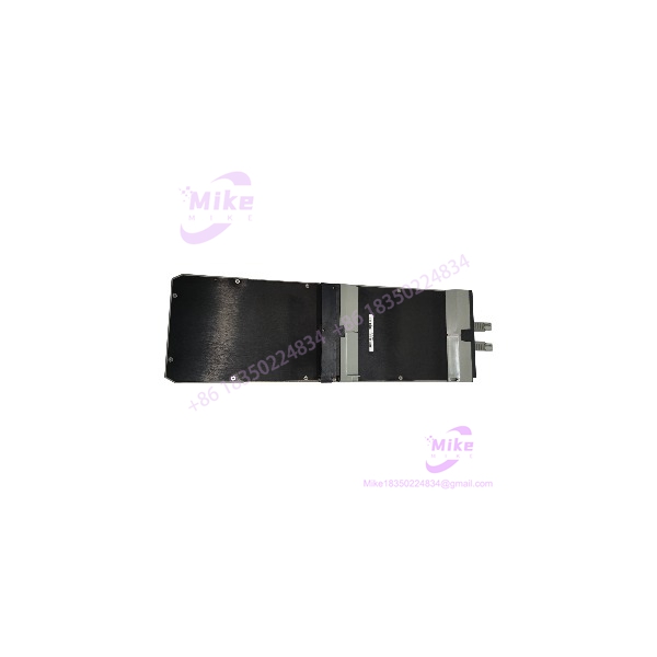
FBM12
Key Technical Specifications
- Manufacturer: Foxboro / Invensys
- Model: FBM12
- System: I/A Series DCS
- Product Type: Contact/DC Expansion Input Interface Module
- Input Channels: 16 independent channels
- Input Function: Contact sensing or DC voltage monitoring
- Input Filtering: 4, 8, 16, or 32 ms configurable
- Fieldbus Connection: Via supporting expandable main FBM
- Input Isolation: 1250 VAC withstand between any channel and earth under the specified one-minute test
- Redundant Module Supply: 26–42 VDC
- Power Consumption: 7 W maximum when considered as the main-module configuration; main-plus-expansion configurations are specified separately
- Operating Temperature: 0 to 60°C
- Storage Temperature: -40 to +70°C
- Relative Humidity: 5–95%, noncondensing
- Operating Altitude: -300 to +3,000 m
- Storage Altitude: -300 to +12,000 m
- Contamination Rating: Class G3, harsh environment
- Approximate Mass: 1 kg
- Mounting: I/A Series 1×8 mounting structure / compatible field enclosure arrangements
- Associated Main Module: FBM07
- Expansion Relationship: depends on the supporting main FBM for Fieldbus communication
The published Foxboro specification states that the environmental and physical specifications apply to both FBM07 and .
Input Configuration
The family uses two principal configurations:
FBM12B — Contact Sensor
- Open-circuit excitation: approximately 24 VDC ±10%
- Intended for contact-sensing applications
- Short-circuit current is limited by the input circuitry
- ON/OFF states are determined by the resistance of the external contact circuit
FBM12A — DC Voltage Monitor
- Intended for monitoring DC voltage presence/absence
- Input thresholds depend on the exact module configuration and termination arrangement
- The associated FBM07/ specification should be used rather than assuming a generic 24 VDC input threshold
The original documentation explicitly labels these configurations FBM12A (voltage monitor) and FBM12B (contact sensor).
Global Sourcing & Live-Test SOP
1. Inbound Verification
For a used or surplus , identification should begin with the complete hardware configuration.
- Confirm the module marking is .
- Record the complete part number and revision.
- Verify whether the unit is an A or B configuration where applicable.
- Photograph the module and its termination interface.
- Inspect connectors for bent, recessed, or oxidized contacts.
- Check the PCB for corrosion, contamination, overheating, or previous repairs.
- Record serial/date information.
- Identify the associated FBM07 or other approved supporting main module.
- Verify the installed termination hardware.
The most common procurement mistake is treating as an independent Fieldbus module simply because it has the same general FBM physical format.
2. Live Simulation
A meaningful functional test requires a compatible I/A Series setup.
Recommended checks include:
- Verify the supporting main FBM.
- Confirm redundant Fieldbus communication through the main module.
- Verify the is recognized by the control system.
- Apply controlled contact or DC input signals.
- Test all 16 input channels.
- Verify ON/OFF state transitions.
- Check the selected 4/8/16/32 ms input filter.
- Confirm channel status indications.
- Verify stable communication during extended operation.
Do not describe a simple power-on test as a complete functional test.
3. Diagnostics
Recommended acceptance checks include:
- Main-module-to-expansion-module communication.
- Input-state verification on all 16 channels.
- DC threshold testing where applicable.
- Contact resistance simulation.
- Input-filter response.
- Supply-voltage measurement.
- Connector continuity.
- Intermittent wiring/connector testing.
- Extended thermal operation for critical process applications.
A calibrated multimeter is appropriate for DC-voltage and continuity checks. A controlled switch simulator or isolated signal source is preferable for repeatable channel testing.
4. Final Preparation
Before shipment:
- Clean the module using an electronics-safe process.
- Protect connectors against ESD and contamination.
- Record model, revision, serial information, and test status.
- Package in ESD-safe material.
- Protect the termination interface against mechanical impact.
- Clearly distinguish tested, refurbished, used, and untested condition.
Do not claim factory-sealed or factory-tested status without supporting documentation.
Field Engineer’s Pitfall Guide
❗ is not a standalone Fieldbus module:
The is the expansion counterpart to . The main FBM communicates independently with the I/A Series Fieldbus, while the expansion module communicates through that supporting main module.
❗ Verify FBM12A versus FBM12B:
The A configuration is associated with DC voltage monitoring, while the B configuration is associated with contact sensing. Do not copy the field wiring from one configuration to another without checking the termination and system documentation.
❗ Do not substitute a newer 16-channel DI module blindly:
Modern Foxboro I/A Series modules may have different Fieldbus interfaces, termination assemblies, diagnostics, and migration requirements. The belongs to the legacy 100 Series architecture; physical similarity does not establish electrical or software compatibility. Schneider Electric categorizes this documentation under the mature I/A Series hardware portfolio.
Intent-Driven FAQ
What is the Foxboro ?
The is a Foxboro I/A Series Contact/DC Expansion Input Interface Module providing 16 independent discrete input channels.
How many inputs does have?
It provides 16 independent input channels.
Is an analog input module?
No. is a discrete/contact/DC input expansion module. It is not intended for conventional 4–20 mA, thermocouple, or RTD measurement.
What is the difference between and ?
is the expandable main Contact/DC Input Interface Module, while is its expansion input counterpart. The main module connects independently to the I/A Series Fieldbus; the expansion module depends on the main module.
Does support contact inputs?
Yes. The can be configured for contact-sensor operation. The B configuration is specifically identified for contact sensing.
Can monitor DC voltage?
Yes. The A configuration is intended for DC voltage monitoring. The exact field voltage and termination configuration should be verified against the complete part number and installed system documentation.
What is the input filter time?
The documented configurable filter settings are 4, 8, 16, and 32 ms.
Is obsolete?
It belongs to the mature/legacy Foxboro I/A Series 100 FBM architecture. Schneider Electric currently categorizes the relevant / documentation under its mature I/A Series hardware documentation.
What should I provide when sourcing a replacement ?
Provide the complete part number, revision, A/B configuration if marked, associated /main module, termination assembly, and photographs of the module label and connectors. This is substantially safer than ordering from the abbreviated “” designation alone.





