

Description
Emerson EPRO PR6424/003-110 | Eddy Current Probe Assembly
Architect’s Product Breakdown
The Emerson EPRO PR6424/003-110 + CON021 is a non-contact eddy-current measurement assembly used in rotating machinery monitoring systems. The probe detects changes in the gap between its sensing face and a conductive shaft target. The CON021 signal converter processes the probe signal into a voltage proportional to the measured gap, allowing compatible monitoring equipment to calculate shaft position and vibration. Typical applications include steam turbines, gas turbines, compressors, pumps, and other critical rotating equipment.
The /003-110 suffix identifies a specific probe configuration; it should not be treated as interchangeable with every PR6424 variant. Published product information identifies this assembly with an 8 mm probe, 3 m cable, and 4 mm total measuring span, with a listed sensitivity of 2 V/mm. Confirm these configuration-specific values against the OEM documentation supplied with the actual unit before using them for engineering calculations. The broader PR6424 family also includes 16 mm sensor configurations, so family-level specifications must not be applied indiscriminately to this model.
For legacy machinery protection systems, the important issue is calibration compatibility, not simply whether the connector fits. Verify the probe cable assembly, converter type, supply polarity, analog output scaling, target material, and receiving monitor configuration. A replacement that produces a voltage can still report the wrong shaft displacement if its sensitivity or calibration differs from the installed assembly.
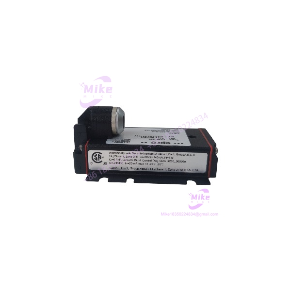
PR6424/003-110+CON021
Key Technical Specifications
| Parameter | Specification |
|---|---|
| Probe model | PR6424/003-110 |
| Converter model | CON021 |
| Measurement principle | Eddy-current proximity sensing |
| Probe diameter | 8 mm, as listed for this configuration |
| Cable length | 3 m, as listed for this configuration |
| Total measuring span | 4 mm, as listed for this configuration |
| Nominal sensitivity | 2 V/mm, per the configuration-specific product listing; verify OEM calibration |
| Linearity | ≤ 1.5%, per the configuration-specific product listing |
| Converter frequency response | 0–20 kHz at −3 dB |
| Converter rise time | Less than 15 µs |
| Converter supply | −23 to −32 VDC for the −4 to −20 V output configuration |
| Alternative output configuration | −2 to −18 VDC, with the corresponding supply range |
| Converter operating temperature | −30°C to +100°C |
| Converter enclosure rating | IP20 |
| Sensor connection | Self-locking LEMO connector on the CON021 |
| Output interface | Analog voltage to compatible machinery monitoring equipment |
The converter specifications above are published for the CON021 family. Probe-specific values are identified separately because the exact /003-110 configuration must be verified before commissioning.
Field Engineer’s Pitfall Guide
Warning 1 — Do not assume the standard PR6424 sensitivity applies to this suffix.
Published information for the broader 16 mm PR6424 family specifies 4 V/mm, while the product listing for this 8 mm /003-110 assembly specifies 2 V/mm. These values must not be mixed. Confirm the complete probe and converter calibration before entering sensitivity into the machinery monitor.
Warning 2 — Verify the output polarity and channel scaling.
The CON021 uses a negative-voltage output configuration. Check the receiving monitor’s input range, polarity, scaling, and alarm thresholds before returning the channel to service. A wiring or scaling mismatch can cause an incorrect displacement reading even when the converter is powered and producing a signal.
Warning 3 — Check the physical probe installation before commissioning.
Confirm the mounting arrangement, cable routing, target material, and installation gap against the applicable OEM procedure. Do not transfer mounting dimensions or gap settings from a different PR6424 suffix without verification. Avoid tight cable bends, crushed cable sections, and damaged connectors.
QA & Testing SOP
- Visual and origin inspection: Verify OEM markings, model and serial numbers, connector condition, cable jacket, sensing face, and evidence of prior installation or repair.
- Electrical inspection: Check the converter supply polarity and voltage, terminal condition, and specified output configuration.
- Live functional test: Connect the probe to the matching CON021 and use a suitable calibrated target fixture to test the measurement response.
- Signal verification: Check sensitivity, linearity, output stability, and response across the specified measuring span. Confirm the signal at the receiving monitor input.
- Documentation: Record serial numbers, the exact configuration, test results, and available calibration records. Firmware recording is generally not applicable to this analog probe-and-converter assembly.
- Packaging: Protect the sensing face and connector, secure the cable against crushing or excessive bending, and use appropriate protective packaging.
Acceptance requirement: Do not approve this assembly for a trip-critical application solely because it powers up. Require functional test results and confirm calibration compatibility with the installed monitoring channel.
Technical FAQ
Q1. Is PR6424/003-110 + CON021 interchangeable with PR6424/010-110 + CON021?
Not automatically. Different suffixes can identify different probe constructions, cable configurations, and calibrated measurement characteristics. Verify the complete ordering code and OEM documentation before substitution.
Q2. Does the CON021 need firmware flashing?
No routine firmware flashing is specified for the CON021 analog signal converter. Check probe compatibility, converter configuration, power supply, and output scaling instead.
Q3. Can I replace the probe while the turbine is running?
Do not assume online replacement is permitted. Disconnecting the probe may interrupt a machinery protection channel or trigger an alarm or trip. Follow the plant’s approved maintenance, isolation, and bypass procedures.
Q4. Will the sensor retain its configuration after power loss?
The probe and CON021 are analog hardware, not a programmable PLC controller. Monitoring-system channel settings and trip logic reside in the receiving equipment. Verify the restored signal and channel configuration after power returns.
Q5. Does new-surplus stock include an OEM warranty?
Not necessarily. New-surplus describes the sales condition, not the warranty status. Obtain written confirmation of condition, functional testing, warranty provider, coverage period, and return terms.





