


Description
Westinghouse 1C31129G03 | Direct Replacement 16-Bit AO Card
Product Introduction
When a modulating steam valve or primary draft fan hesitates during load changes, the root cause is rarely the controller CPU—it usually tracks back to DAC drift or output driver degradation on an aging loop card. The Emerson 1C31129G03 is not a generic current driver; it is a high-precision, 8-channel Analog Output Electronics Module (EMOD) engineered specifically for critical process loops in Ovation DCS architectures. It transforms digital system commands into highly repeatable 0–20 mA analog control signals, ensuring precise final control element positioning across high-stress industrial operations.
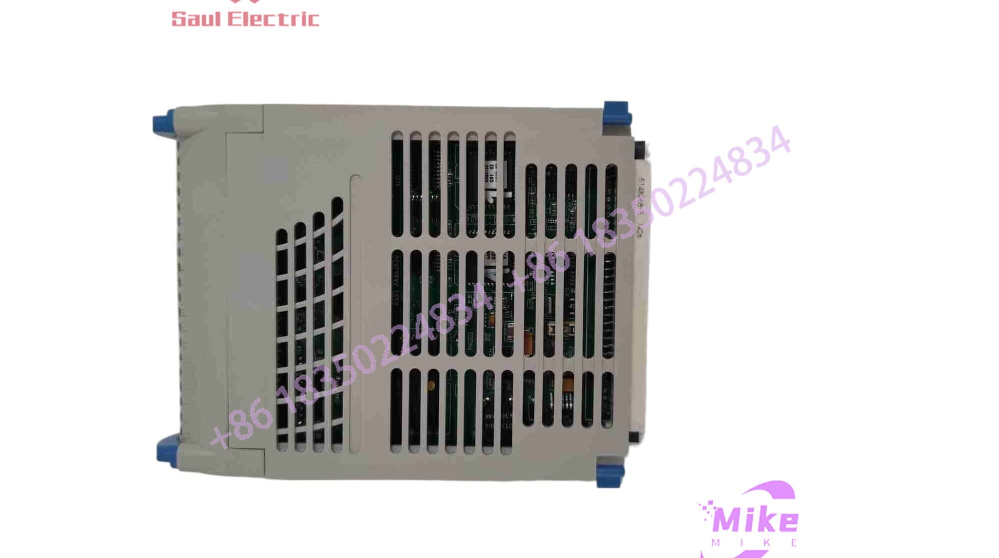
1C31129G03
Operating on a 16-bit converter architecture, this card delivers an accuracy envelope of ±0.05% of full scale—stopping output hunting cold on sensitive flow, pressure, and temperature loops. Optical channel isolation prevents field ground loops and high-voltage common-mode spikes from backing up into the backplane, protecting the local node logic. Whether your facility manages power generation boiler feeds, water treatment dosing, or refinery cracking units, maintaining a verified 1C31129G03 on the spare parts rack guarantees that a failed output driver won’t force a full system trip.
Key Technical Specifications
| Parameter | Technical Specification |
| OEM Part Number | 1C31129G03 |
| System Family | Emerson / Westinghouse Ovation DCS |
| Module Type | Analog Output Electronic Module (EMOD) |
| Output Channels | 8 isolated current loops |
| Current Output Range | 0 to 20 mA (field configurable for 4 to 20 mA range) |
| D/A Converter Resolution | 16 bits |
| Output Accuracy | ±0.05% of full scale at 25°C |
| Dielectric Strength | 1000V AC/DC (channel-to-channel and channel-to-logic) |
| Main Power Consumption | Typical 2.4 W, Maximum 3.125 W |
| Auxiliary Power (24VDC) | Typical 3.84 W (when paired with standard base/PMOD) |
| Operating Temperature | 0°C to +60°C (32°F to +140°F) |
| Humidity Range | 0% to 95% non-condensing |
Application Scenarios & Pain Points
Scenario 1: Field Diary – Turbine Bypass Valve Hunting
A cogeneration plant in Ohio experienced continuous pressure oscillations on its turbine bypass line. The positioner on the bypass valve was constantly hunting between 42% and 46% stroke, creating thermal stress on the downstream headers. A scope check revealed that Channel 3 on an older analog output card was generating a 0.8 mA high-frequency ripple due to thermal aging on the output driver transistor. Swapping in a fresh Emerson 1C31129G03 restored smooth, flatline 4–20 mA current stability, locking valve position down to within ±0.1% stroke instantly.
Scenario 2: With vs. Without Dedicated Isolated AO Cards
- Without 1C31129G03: Unisolated or low-resolution analog outputs suffer from ground loop interference, temperature-induced calibration drift, and stepped control responses—resulting in valve packing wear, process cycling, and unstable loop tuning.
- With 1C31129G03: 16-bit resolution delivers smooth, continuous signal transitions. Onboard 1000V galvanic isolation ensures that field noise, ground potential differences, or sensor shorts never reach the main Ovation backplane.
Scenario 3: High-Reliability Industrial Loops
- Boiler Feedwater Control: Driving modulating actuator positioners where fractional-milliamp shifts dictate feedwater drum levels under heavy steam demands.
- VFD Speed Referencing: Transmitting precision 0–10V / 4–20mA speed commands to large 4160V Variable Frequency Drives in high-vibration draft fan environments.
QA & Live Testing SOP (Trust Signal)
Every replacement 1C31129G03 module passes a strict 4-stage quality control routine before entering static-shielded storage:
- Visual & Structural Inspection: Microscopic audit of all gold-plated edge-connector pins, surface-mount components, and solder runs to confirm zero trace lifting, thermal discoloration, or micro-fractures.
- Current Linearity & DAC Calibration: Using a Fluke 754 Documenting Process Calibrator, we command each of the 8 channels through a 5-point ramp test (0mA, 5mA, 10mA, 15mA, 20mA). We verify linearity remains strictly within the ±0.05% full-scale tolerance window.
- Live Ovation Rack Handshake: The module is snapped onto an active Ovation test rack running a live controller drop. We execute fast step-change output commands to verify zero channel cross-talk, instant DAC response, and clean diagnostic status bit updates.
- ESD Safe Shielding: Approved modules are sealed in static-shielding bags with moisture desiccant and packed in custom heavy-duty foam containers for safe international transport.
Field Engineer’s Pitfall Guide
❗ WARNING 1: Verify Hardware DIP Switch & Software Mappings
The 1C31129G03 supports a raw 0–20 mA output span. If your field device requires a standard 4–20 mA signal, ensure that the channel scaling parameters in the Ovation Developer Studio / Control Builder software are set to clamp zero at 4 mA. Sending an un-scaled 0 mA signal to a 4–20 mA valve positioner will trip a “Loss of Signal” fault on the field device!
❗ WARNING 2: De-Energize Field Power Before Seating
While top-level Ovation EMOD cards generally support hot-swapping, inserting the 1C31129G03 at a steep angle onto a live base unit can arc the backplane power pins. Always align the card guides parallel to the base and push firmly until both top and bottom latching mechanism click.
❗ WARNING 3: Check External Load Loop Resistance (R_{load})
Ensure the total loop resistance (field wiring resistance plus device input impedance) on any channel does not exceed the drive capability of the 24 VDC auxiliary loop supply (typically 600–750 ohms max). Exceeding maximum load resistance will cause the current output to saturate before reaching full 20 mA output.
Intent-Driven FAQ
Q: Is the 1C31129G03 compatible with older Westinghouse Ovation systems?
A: Yes. The 1C31129G03 maintains complete backward and forward compatibility across legacy Westinghouse Ovation cabinets as well as modern Emerson Ovation DCS architectures.
Q: What is the difference between the G01, G02, and G03 revisions of this card?
A: Suffix revisions (such as G01 vs. G03) generally designate channel group configurations, output resolution adjustments, or underlying circuit board component updates. Always check your cabinet hardware drawing or software drop configuration before swapping group suffixes to ensure proper signal matching.
Q: Can I use this card to output a 0–10 VDC voltage signal instead of current?
A: The 1C31129G03 is natively designed as a 0–20 mA current output module. To drive a 0–10 VDC input device, a precision 500-ohm shunt resistor can be installed across the field terminal block terminals, converting the 0–20 mA signal to a 0–10 VDC drop—though a dedicated voltage PMOD/EMOD is preferred for noise immunity.
Q: What does a red diagnostic LED on the front faceplate mean?
A: A red error LED indicates an internal hardware fault, a loss of backplane communication with the controller, or an open-circuit fault detected on one of the active current output loops.
Q: What warranty coverage comes with this module?
A: Every 1C31129G03 unit comes backed by our comprehensive 12-month full replacement warranty. If a channel fails calibration or drops offline during commissioning, we replace it immediately from our emergency warehouse stock.





