

Description
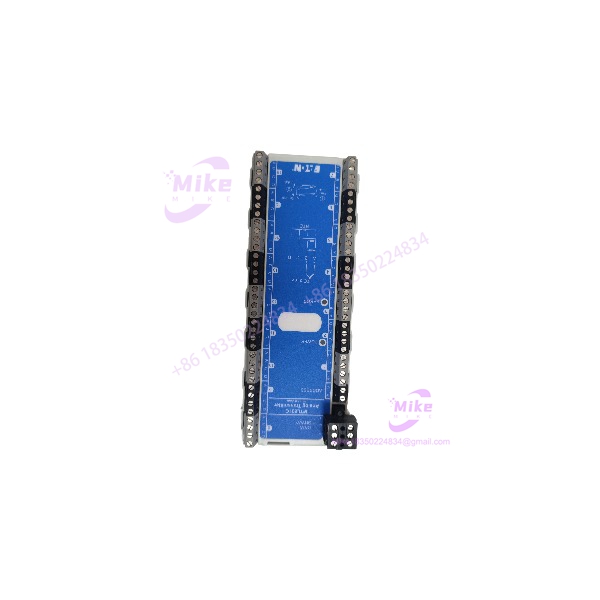
Eaton MTL831C | 16-Channel Analog Transmitter
Architect’s Product Breakdown
Within the MTL830C temperature multiplexer architecture, the MTL831C serves as the field-side signal acquisition and transmission device. It accepts up to 16 sensor inputs and sends measurement data over a shared data highway to a compatible receiver. This arrangement reduces the need to run individual sensor signal cables all the way back to the control room, particularly in distributed process installations where conventional point-to-point wiring becomes expensive.
The input architecture supports mixed sensor types, including thermocouples, millivolt signals, RTDs, and potentiometers. Individual channels are configured for the required input type. The data highway carries both communications and power, with a published maximum distance of 2 km under suitable installation conditions. The receiver determines the control-system interface: the MTL838C provides Modbus serial communication over RS-485, while the MTL838C-MBT provides Modbus TCP over Ethernet. These receiver models are not interchangeable from a network-configuration
For legacy DCS and PLC maintenance, the MTL831C is especially relevant where hazardous-area temperature measurements must remain in service without extensive field rewiring. However, do not treat it as a conventional 4–20 mA analog input card. Its measurements reach the controller through the multiplexer receiver and associated communications mapping. Before replacing a unit, document the existing channel assignments, sensor types, Modbus register mapping, receiver configuration, and intrinsic-safety arrangement. A replacement that powers up successfully can still deliver incorrect process values if these settings are mismatched.
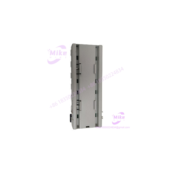
MTL831C
Key Technical Specifications
| Parameter | MTL831C specification |
|---|---|
| Manufacturer | Eaton, MTL product line |
| Model | MTL831C |
| System family | MTL830C Temperature Multiplexer |
| Input capacity | 16 channels |
| Supported inputs | Thermocouples, millivolt sources, RTDs, potentiometers |
| RTD wiring | 2-wire, 3-wire, or 4-wire |
| Millivolt measurement range | ±100 mV |
| Thermocouple types | B, C, E, J, K, N, R, S, T; additional options require confirmation |
| RTD measurement ranges | Depends on sensor type; includes Pt100 from −200°C to +850°C |
| Typical response time | 500 ms from input to Modbus register |
| Data highway | Single shielded, twisted-pair cable recommended |
| Maximum highway distance | Up to 2 km, installation-dependent |
| Power supply | Loop-powered through the data highway; no separate hazardous-area supply required |
| Working temperature | −40°C to +70°C |
| Storage temperature | −40°C to +85°C |
| Mounting | 35 mm T-section DIN rail; vertical mounting plane required for specified accuracy |
| Weight | Approximately 0.26 kg |
| Intrinsic-safety classification | Published rating: Ex ia IIC T4 Ga, subject to installation conditions |
| Receiver compatibility | MTL838C or MTL838C-MBT, according to required communications interface |
Specifications should be checked against the applicable product revision and certification documentation before use in a safety-related or hazardous-area installation.
Field Engineer’s Pitfall Guide
Warning 1 — Do not overlook the receiver and data highway.
The MTL831C is one part of a system. Confirm that the installed receiver is compatible and correctly configured. One or two transmitters may be connected to a single MTL838C receiver, subject to the system design. Check the receiver model, channel mapping, communications settings, and required isolator/power-supply arrangement before commissioning.
Warning 2 — Sensor configuration must match the field wiring.
A channel configured for a 4-wire RTD will not produce valid measurements if the sensor is wired or configured as a thermocouple or 2-wire RTD. Check the sensor type, terminal assignments, lead compensation, polarity, and engineering-unit scaling. Do not rely solely on a plausible-looking temperature value; verify representative channels against a known reference.
Warning 3 — Mounting orientation affects measurement accuracy.
The manufacturer specifies mounting on a vertical plane using vertical or horizontal DIN rail to meet the published accuracy requirements. Nearby heat sources can create temperature gradients and introduce measurement error. Allow suitable thermal separation and follow the installation manual. Also verify that the complete installation satisfies the applicable hazardous-area certification requirements.
A common troubleshooting trap in multiplexed temperature systems is replacing the field transmitter when the real problem is a receiver configuration or sensor-wiring mismatch. Record the existing channel configuration and capture baseline readings before disturbing the installation. That simple step can prevent unnecessary replacement work and prolonged fault-finding.
QA & Testing SOP — Transparency
The following is a recommended acceptance procedure, not a claim that a particular unit has already passed testing.
1. Visual and origin inspection
- Verify the complete model marking, serial information, terminal arrangement, and physical condition.
- Inspect the housing, terminals, mounting clips, and labels for damage, corrosion, or evidence of unauthorized repair.
- Record the supplied condition as new surplus, used, or refurbished.
2. Electrical and configuration checks
- Confirm that the unit is suitable for the intended MTL830C system configuration.
- Inspect sensor terminals and data-highway connections.
- Verify the receiver model, channel assignments, and required isolation and power-supply components.
- Check the applicable intrinsic-safety entity parameters and installation documentation.
3. Functional testing
- Where suitable equipment is available, test representative supported inputs using calibrated sensor simulators or reference instruments.
- Verify input selection, measurement response, sensor-fault reporting, and communication with the compatible receiver.
- Check representative Modbus register values and confirm that readings agree with the configured sensor types and scaling.
- Record test conditions, results, and any untested functions.
4. Documentation and packaging
- Record the product identification, test date, inspection results, and any limitations.
- Protect terminals and electronics during handling and shipping.
- Use suitable electrostatic-discharge precautions where applicable.
- Package the unit to prevent moisture exposure, vibration damage, and terminal deformation.
Buyer note: Request an actual test report if live testing is advertised. A seller’s general testing procedure is not evidence that the specific unit passed it.
Technical FAQ
Q1: Can the connect directly to a PLC analog input card?
Not as a conventional direct-wired analog input. The transmits its measurements over the data highway to a compatible receiver. The controller then obtains the values through the receiver’s supported communications interface and configured data mapping.
Q2: Can I replace an with an -PS?
The principal distinction is the input terminal arrangement: the uses fixed screw-terminal inputs, while the -PS uses pluggable screw-terminal inputs. Before substitution, verify the existing wiring arrangement, terminal compatibility, mounting requirements, and applicable product documentation.
Q3: Does the require a separate 24 VDC supply in the hazardous area?
The transmitter is loop-powered through the data highway and does not require a separate hazardous-area power supply under the documented system arrangement. The complete circuit must still comply with the required entity parameters and intrinsic-safety installation conditions.
Q4: Will the retain its configuration after a power loss?
Do not assume that all system settings are stored in the transmitter. Channel configuration, receiver settings, communications mapping, and host-controller configuration must be assessed separately. Keep a verified backup of the receiver and controller configuration and confirm the recovery procedure before a planned shutdown.
Q5: Can I install the in Zone 0?
The published product classification supports Zone 0 applications under the specified intrinsic-safety conditions. That does not automatically approve every installation. Confirm the exact equipment marking, certification validity, associated apparatus, wiring parameters, and installation requirements for the actual hazardous-area classification.





