Description
DEIF FAS-2R | Automatic Generator-to-Bus Synchronizer
Product Introduction
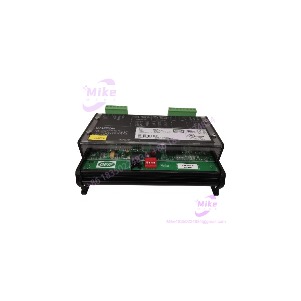
The DEIF FAS-2R is a dedicated full-automatic synchronizing relay for generator paralleling applications. Its job is straightforward but electrically unforgiving: establish acceptable phase relationship between the generator and the bus before the generator breaker is permitted to close.
This is not simply a voltage-monitoring relay. The FAS-2R belongs in the synchronization chain of a generator switchboard, where generator voltage, bus voltage, frequency, and phase relationship must be evaluated before a closing command is issued. Independent technical documentation identifies the FAS-2R specifically as the synchronizing relay used to automatically phase a diesel generator onto the electrical network.
The model is also repeatedly documented as a “full-auto synchronising relay” and “auto synchronizing relay,” including a unit identified as DEIF FAS-2R, No. 18146-6.
For procurement, the important point is age and variant control. FAS-2R is a legacy DEIF design, and currently available DEIF synchronization products use different model families. Do not assume a modern DEIF synchronizer is a pin-for-pin replacement simply because its functional description looks similar.
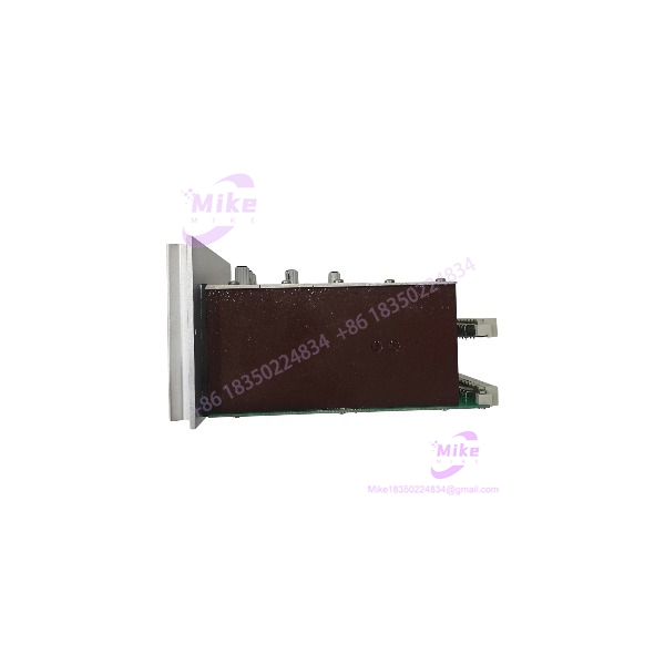
FAS-2R
Key Technical Specifications
- Manufacturer: DEIF A/S
- Model:
- Product Type: Full-automatic synchronizing relay
- Primary Function: Generator synchronization
- Application: Generator-to-bus/grid paralleling
- Control Role: Synchronization permissive / breaker-closing control
- Measurement Domain: Generator and bus electrical parameters
- Synchronization Objective: Establish acceptable electrical synchronism before breaker closing
- Typical Installation: Generator switchboards, power-generation systems, marine electrical systems, and industrial generator plants
- Documented Type Designation:
- Example Identification: No. 18146-6
- Condition in Surplus Market: Commonly encountered as used/legacy equipment
- Exact Supply Voltage: Verify from the individual nameplate/revision
- Exact Voltage Measurement Range: Verify from the individual nameplate/revision
- Exact Relay Contact Ratings: Verify from the original DEIF documentation for the installed variant
- Exact Synchronization Window: Verify from the original DEIF settings/documentation
The last four items are intentionally not filled with generic numbers. Older DEIF relay families were produced in multiple electrical variants, and the available evidence does not provide enough reliable primary documentation to establish those values for every unit.
Synchronization Function
The operating sequence of an automatic synchronizing relay is fundamentally different from a simple voltage relay.
A generator that is ready to connect to a live bus must satisfy several conditions before breaker closing:
- Generator voltage must be within the permitted relationship to bus voltage.
- Generator frequency must be sufficiently close to bus frequency.
- Phase angle must be inside the permitted synchronization window.
- The generator must be moving toward the correct phase relationship.
- Breaker closing must account for breaker operating time.
- The synchronization relay must issue the closing command at the appropriate point.
The performs the synchronization-relay function within this architecture.
In a practical generator installation, the relay therefore sits between the generator measurement circuits and the generator circuit-breaker control circuit. Incorrect measurement wiring can be more dangerous than a simple loss of indication because the synchronizer is directly involved in determining when paralleling is permissible.
Typical Generator Application
A representative installation can be structured as:
- Diesel or gas generator
- Generator AVR
- Generator governor
- Generator voltage transformers
- Busbar voltage transformers
- DEIF synchronizing relay
- Generator circuit breaker
- Generator protection relays
- Generator control/start-stop system
- Load-sharing or power-management system
The is concerned specifically with the synchronization step.
The governor controls speed/frequency. The AVR controls generator voltage. The synchronizing relay evaluates the relationship between generator and bus and determines when the breaker can be commanded to close.
That separation of responsibilities is important when troubleshooting. If the generator is consistently drifting in frequency, changing the synchronizer itself may not solve the problem. Likewise, if phase displacement is unstable because of a voltage-transformer wiring error, replacing the relay can mask the real fault without correcting it.
Global Sourcing & Live-Test SOP
Inbound Verification
For a surplus , begin with the physical identification.
Record:
- Exact designation
- Complete nameplate
- Serial number
- DEIF order/identification number
- Hardware or revision information
- Supply-voltage marking
- Terminal arrangement
- Factory labels
- Any auxiliary identification such as 18146-6
Photograph the front and rear before cleaning.
Do not remove original labels during refurbishment.
Electrical Inspection
Before applying power:
- Inspect terminal blocks for cracking or corrosion.
- Check for loose terminals.
- Inspect PCB areas for contamination.
- Look for heat discoloration around relay contacts.
- Check terminal-to-terminal insulation where appropriate.
- Verify that the expected supply voltage matches the specific unit.
- Inspect the synchronization measurement inputs for damaged wiring or connectors.
A used synchronizing relay should not be energized directly on an unknown test supply.
Functional Simulation
A proper test should reproduce generator and bus conditions using controlled electrical test equipment.
Recommended checks include:
- Apply the specified auxiliary supply.
- Simulate generator voltage.
- Simulate bus voltage.
- Introduce controlled frequency difference.
- Introduce controlled phase-angle difference.
- Verify synchronizing indication/output behavior.
- Test breaker-close permissive logic.
- Verify response when voltage is outside the acceptable region.
- Verify response when frequency difference is excessive.
- Verify behavior when phase relationship is outside the permitted window.
- Record relay output behavior throughout the test.
Where a suitable relay test set is available, use synchronized voltage sources rather than attempting to simulate phase relationships with improvised bench wiring.
Breaker-Close Verification
The final functional test should examine the complete synchronization chain.
The test rack should include:
- Generator-side voltage simulation
- Bus-side voltage simulation
- Frequency control
- Phase-angle control
- Breaker-command monitoring
- Timing measurement
- Event recording
The objective is to verify that the does not simply indicate “synchronized,” but produces the expected control output under the correct electrical conditions.
Final Preparation
After testing:
- Record the exact tested configuration.
- Record measured operating behavior.
- Preserve the original identification label.
- Protect terminals from contamination.
- Use ESD-safe packaging for electronic assemblies.
- Package the relay against vibration and impact.
- Include revision and serial information in the QC record.
For a generator-critical spare, retain the test report with the purchase documentation.
Field Engineer’s Pitfall Guide
❗ Do not replace the based only on the words “automatic synchronizer.”
Synchronization relays are not universally interchangeable. Terminal assignments, sensing voltage, auxiliary supply, breaker-control outputs, synchronization settings, and timing behavior must all match the original installation.
❗ Do not troubleshoot synchronization by adjusting the relay first.
If the generator governor cannot hold frequency, or the AVR produces unstable voltage, the synchronizer may continuously refuse breaker closing. Confirm the generator’s speed and voltage control loops before changing synchronization parameters.
❗ Verify the voltage-transformer phase sequence.
A phase-sequence or VT-wiring error can produce persistent synchronization failure even when generator voltage and bus voltage appear correct when measured independently. Phase relationship is the parameter that ultimately matters for breaker closing.
Intent-Driven FAQ
Q1. What is the DEIF ?
The DEIF is a full-automatic synchronizing relay used to synchronize a generator with an electrical bus before paralleling. Independent technical documentation explicitly identifies it as a generator synchronizing relay.
Q2. What does the control?
Its principal role is the synchronization and breaker-closing permissive function. It evaluates the electrical relationship between the generator and the bus so that the generator breaker can be closed at the appropriate synchronization point.
Q3. Is the a generator controller?
No. It is more accurately described as a synchronizing relay. The generator governor, AVR, protection relays, and plant control system may perform other functions that work alongside the .
Q4. Can the be used on diesel generators?
Yes. Independent documentation specifically describes a diesel-generator installation using the DEIF to automatically phase the generator onto the electrical network.
Q5. Is the still a current DEIF product?
It should be treated as a legacy model for sourcing purposes. Current DEIF documentation prominently covers newer synchronizing products, while is encountered primarily through surplus and used-equipment channels. Verify availability and replacement compatibility with the exact installed system.
Q6. What should I verify before purchasing a used ?
Verify the complete nameplate, identification number, auxiliary supply, sensing-voltage configuration, terminal arrangement, relay-contact configuration, revision, and the existing generator switchboard wiring diagram. A functional synchronization test is strongly recommended before installing a used unit into a live generating system.
Q7. Is the suitable as a direct replacement for another DEIF synchronizer?
Not automatically. Even within DEIF’s product range, different synchronizer families have different electrical interfaces and functionality. Treat the exact variant and the original switchboard drawing as the compatibility reference.