Description
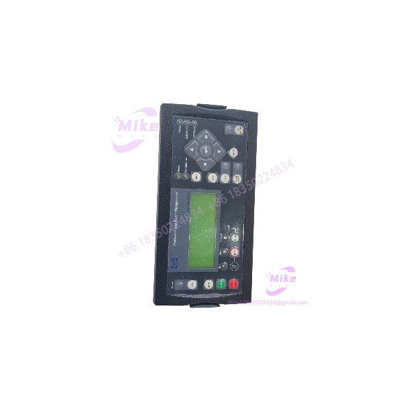
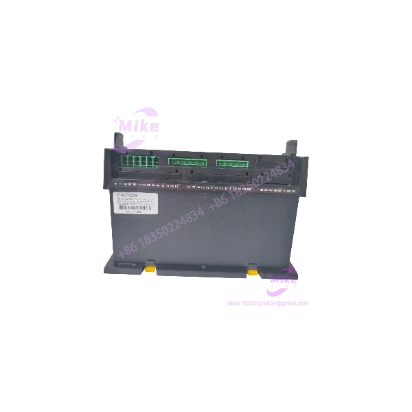
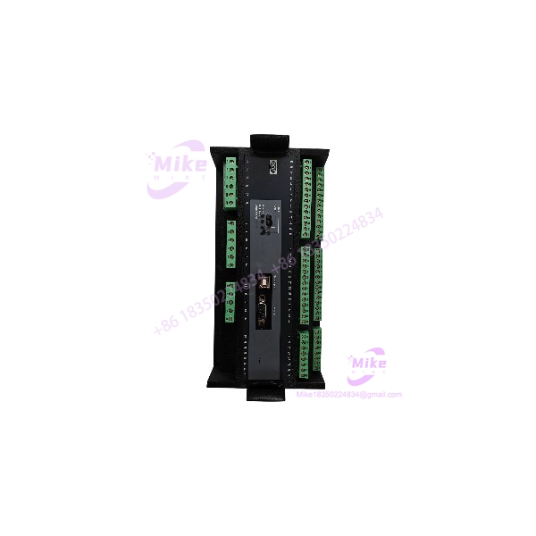
DEIF PPU-3 | Power Protection Unit & Synchronizer, New
Architect’s Product Breakdown
The DEIF PPU-3 operates as a high-integrity, modular protection and synchronization controller built for complex multi-generator power distribution networks. Positioned directly within marine switchboards and industrial backup power systems, this unit combines traditional discrete relay functions, synchronoscopes, and load-sharing modules into a unified controller. Its peer-to-peer multi-master architecture ensures that if one generator controller drops offline, the remaining units dynamically redistribute load management tasks without requiring a centralized PLC master.
Deploying the PPU-3 requires meticulous configuration of its internal protection curves and communication topologies. Because the hardware interfaces directly with high-voltage potential transformers (PTs) and current transformers (CTs), technicians must verify scaling factors and wiring polarity down to the millivolt. Furthermore, integrating a replacement module onto an active bus demands exact firmware version matching via DEIF utility software to prevent configuration rejection and bus arbitration timeouts.
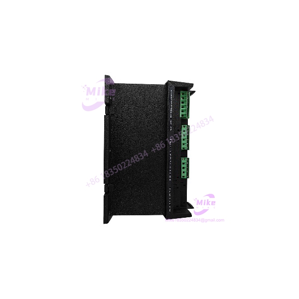
PPU-3
Key Technical Specifications
| Parameter | Specification Details |
| Supply Voltage | 12 / 24 VDC nominal (9 to 32 VDC range) |
| Power Consumption | Approximately 10W nominal |
| Voltage Measurement | Up to 690 VAC direct / PT inputs (True RMS) |
| Current Measurement | 1 A / 5 A secondary CT inputs |
| Frequency Range | 15 Hz to 85 Hz |
| Communication Protocols | Redundant CANbus, Modbus RTU, Ethernet, Profibus (optional) |
| Discrete Inputs / Outputs | Fully configurable digital and relay output channels |
| Synchronization Accuracy | \pm 0.3^\circ phase angle / \pm 0.5\% voltage match |
| Operating Temperature | -20^\circC to +70^\circC |
| Enclosure Protection | IP21 front / IP20 terminal blocks |
Field Engineer’s Pitfall Guide (Unique Value)
- Multi-Master CANbus ID Conflicts: Setting duplicate node addresses on the peer-to-peer CAN network will crash the arbitration loop, causing random generator dropouts. I once spent an entire night troubleshooting a multi-engine switchboard where a replacement module was shipped with the default factory node ID, corrupting the entire load-sharing data stream.
- CT Polarity Reversal: Mixing up the k and l (or S1 and S2) polarities on the current transformer inputs will instantly trigger reverse power or directional fault trips the moment the generator takes load. Always perform a secondary injection test before closing breakers on a fresh install.
- Unregulated Control Bus Dips: Dropping control power below 9 VDC during heavy breaker solenoid activation causes the internal processor to watchdog-reset. Ensure your 24 VDC auxiliary supply is backed by a robust UPS or dedicated battery plant.
QA & Testing SOP (Transparency)
- Visual & Origin Verification: Inspection of factory anti-tamper seals, hardware casting marks, and serial number traceability against OEM databases.
- Live Test Environment: Bench testing on a dedicated multi-node simulator rig powered by regulated 24 VDC supplies with injected three-phase voltage and frequency signals.
- Diagnostics & Handshake Testing: Executing full I/O mapping checks, relay contact actuation under load, and redundant CANbus multi-master communication handshakes.
- Firmware Logging & ESD Packaging: Documenting active firmware revisions, sealing the hardware inside anti-static shielding bags, and packing in custom high-density foam enclosures.
Technical FAQ
- Can I hot-swap a PPU-3 module while the switchboard is energized? No. Disconnecting or replacing this unit on a live system risks compromising bus integrity and causing unintended breaker trips. Always isolate control power and open local disconnects first.
- What software is required to upload site configurations? You must use the official DEIF USW (Utility Software) suite running on a compatible Windows PC connected via USB or Ethernet.
- Does the controller save configurations during a total power failure? Yes, all trip settings, custom logic, and calibration parameters are stored in non-volatile flash memory, protecting data integrity during blackouts.
- Is the PPU-3 backward compatible with older PPU-2 systems? Direct drop-in compatibility is limited due to physical cutout changes, terminal layout differences, and updated communication protocols; a complete engineering review of the wiring harness is required.