Description
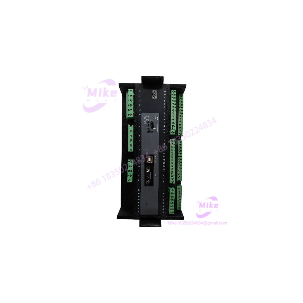
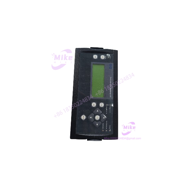
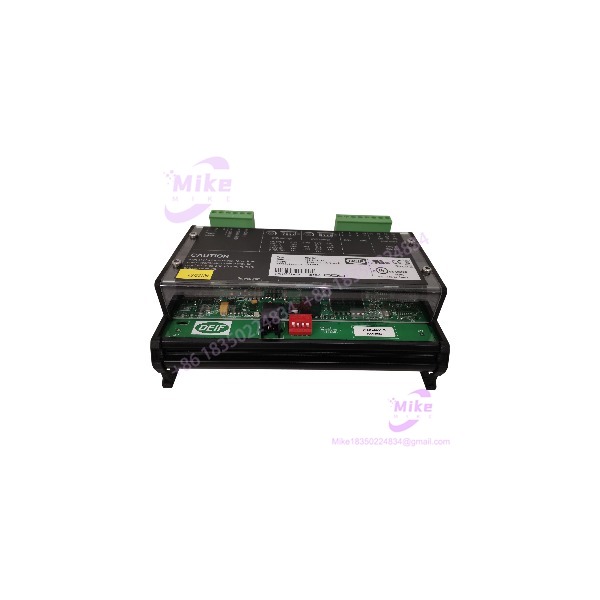
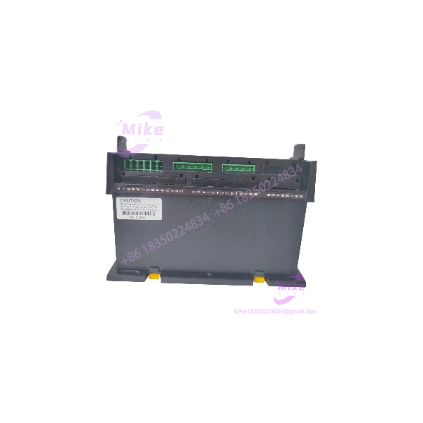
DEIF FAS-113AD | FAS Series Industrial Control Module
Product Introduction
The DEIF FAS-113AD is a legacy DEIF FAS-series hardware assembly. Available industrial-equipment references associate the FAS-113AD designation with the older FAS control-system product family, but detailed primary documentation for this exact suffix is difficult to locate today.
That makes identification discipline more important than a long specification sheet. FAS-113AD should not be treated as interchangeable with another DEIF FAS-series module simply because the front-panel designation looks similar. For a replacement purchase, the complete part number, hardware revision, terminal arrangement, supply requirements, and original application documentation should all be matched.
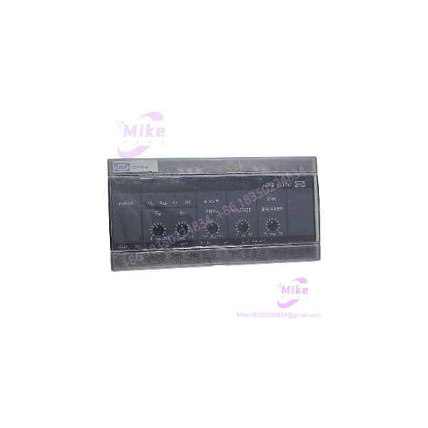
FAS-113AD
Key Technical Specifications
- Manufacturer: DEIF A/S
- Model: FAS-113AD
- Series: FAS
- Equipment Type: Legacy control / relay module
- Primary Role: FAS-series electrical control and monitoring
- Application Area: Industrial electrical systems and generator-related control environments
- Technology Generation: Legacy DEIF hardware
- Exact Supply Voltage: Verify from nameplate
- Exact Input Configuration: Verify from unit documentation
- Exact Output/Relay Configuration: Verify from unit documentation
- Exact Contact Ratings: Verify from original DEIF specification
- Exact Dimensions: Verify against the physical unit
- Exact Terminal Assignment: Verify against the installed system drawing
- Firmware/Revision: Verify from the individual unit where applicable
I am intentionally leaving the unverified electrical values open. For obsolete industrial hardware, an incorrect voltage or terminal assignment is considerably more damaging than an incomplete specification.
System Integration Considerations
The FAS-113AD should be evaluated as part of the complete DEIF FAS control architecture rather than as an isolated electronic component.
Before substitution, establish:
- What equipment the original controlled
- Which power supply feeds the module
- Which field signals enter the module
- Which relay or control outputs leave the module
- Whether external relays or contactors are involved
- Whether the unit operates as part of a generator-control panel
- Whether any timing or interlock functions depend on the module
- Whether the replacement must preserve the existing terminal layout
This is especially important for legacy generator and switchgear panels. A module that performs the same general function may still be electrically incompatible.
Global Sourcing & Live-Test SOP
Inbound Verification
For a used , record:
- Complete model marking
- Serial number
- Revision information
- Supply-voltage marking
- Terminal markings
- PCB revision where visible
- Connector type
- Front-panel condition
- Any DEIF identification label
Photograph both sides of the assembly before cleaning.
Electrical Inspection
Before energization:
- Inspect terminals for corrosion.
- Check connectors for bent or damaged contacts.
- Inspect the PCB for heat damage.
- Check for cracked solder joints.
- Look for evidence of previous overvoltage.
- Confirm the intended auxiliary supply from documentation.
- Verify external relay/interface wiring before connecting the module.
Do not apply a guessed voltage merely because another DEIF FAS module uses it.
Functional Test
The preferred test is performed with a controlled test harness based on the original panel drawings.
Recommended checks:
- Controlled power-up
- Input-state simulation
- Output/relay-state verification
- Interlock simulation
- Alarm-state simulation
- Timing verification where applicable
- Contact continuity testing
- Repeated power-cycle testing
- Thermal observation during an extended run
Where the module interfaces with a generator or switchgear system, the test should reproduce the relevant control logic without connecting directly to live high-energy equipment.
Final QC
After successful testing:
- Record the tested supply voltage.
- Record all verified inputs and outputs.
- Record relay/contact behavior.
- Photograph the tested unit.
- Preserve serial-number traceability.
- Use ESD-safe packaging.
- Protect terminals against mechanical damage and contamination.
Field Engineer’s Pitfall Guide
❗ Do not infer the terminal assignment from another DEIF FAS model.
Legacy DEIF product families contain multiple variants with similar naming conventions. Terminal numbers and relay functions must be verified against the exact documentation or the original control-panel schematic.
❗ Do not assume an old unit is electrically healthy because its LEDs or indicators operate.
Relay contacts, power-supply components, electrolytic capacitors, and solder joints can degrade with age. A proper bench test should exercise both inputs and outputs.
❗ Verify the original application before approving a replacement.
If is installed in a generator, switchboard, or other control panel, identify every external circuit connected to it. A replacement that matches the enclosure but changes a contact arrangement can create an interlock or breaker-control problem.
Intent-Driven FAQ
Q1. What is the DEIF ?
The is a legacy DEIF FAS-series control/relay module. Current online documentation for this exact suffix is limited, so the specific electrical configuration should be confirmed from the physical unit and original system documentation.
Q2. Is a modern DEIF controller?
No. It should be treated as legacy DEIF hardware when evaluating procurement, replacement, and lifecycle risk.
Q3. Can another DEIF FAS module directly replace ?
Not automatically. Match the complete part number, revision, supply requirements, terminal assignment, input/output functions, and application wiring before substitution.
Q4. What should be checked on a used ?
Check the nameplate, serial number, revision, connectors, terminals, PCB condition, power-supply requirements, relay contacts, and all I/O functions. A live bench test using the original panel documentation is strongly recommended.
Q5. Can the exact electrical specifications be confirmed from the model number alone?
Not reliably from the currently available evidence. The exact supply voltage, contact ratings, terminal assignment, and timing parameters should be taken from the specific revision documentation rather than inferred from related FAS products.
Q6. Is suitable as a new-system component?
It is better regarded as a legacy replacement/spares component. For a new installation, the appropriate current DEIF product should be selected based on the required control and protection functions.