


Description
DEIF AGC/GS/3 | Automatic Genset Controller
Dynamic Project Introduction
Power generation systems—ranging from emergency marine backup generators to critical industrial standby plants—rely on dependable controllers to manage automatic starts, grid synchronization, and load sharing. The DEIF AGC/GS/3 delivers advanced power management within the established AGC-3 architecture, handling engine protection, breaker controls, and multi-unit balancing with precision.
When replacing legacy power management hardware, matching the exact version and firmware profile of an AGC/GS/3 controller ensures that your safety interlocks, communication loops, and display menus function seamlessly without requiring a system rewrite.
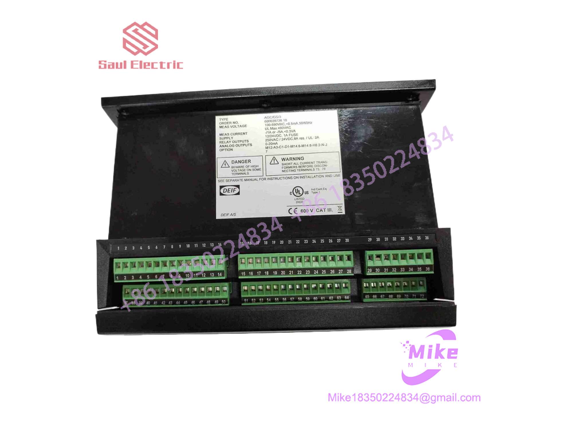
AGCGS3
Key Technical Specifications
| Parameter | Specification Detail |
| Primary Architecture | Microprocessor-based generator control, protection, and synchronization unit |
| System Compatibility | Single and multi-genset applications (Island mode, AMF, Peak shaving, Synchronization) |
| Display & Interface | High-contrast graphical LCD display paired with dedicated menu-navigation and command keys |
| Communication Ports | Multiple CANBus interfaces (for engine ECU communication and internal multi-controller load sharing), RS-485/USB options |
| Measurement Inputs | True RMS voltage and current sensing for generator and busbar, frequency, power factor, and active/reactive power |
| Discrete I/O | Configurable digital inputs/outputs and relay outputs for breaker control, engine start/stop, and alarm routing |
| Approvals & Standards | Marine classification society certified (ABS, DNV, LR, etc.) and industrial CE compliant |
| Mounting & Enclosure | Panel-mount front display unit with rear modular terminal strip connections |
Global Sourcing & Live-Test SOP
Sourcing legacy or surplus power management controllers requires rigorous laboratory validation to ensure microcontroller health, true RMS measurement accuracy, and communication bus stability:
- Inbound Verification: Part numbers, software version tags, and manufacturer serial stickers are audited against authentic DEIF production archives.
- Visual Audit: Front display panels, tactile keypads, and rear plug-in terminal blocks are inspected for physical stress, moisture contamination, or pin corrosion.
- Live Bench Simulation: Units are powered on an isolated test rig using simulated AC voltage and current inputs. We verify true RMS measurement accuracy, display initialization, and internal power supply rail stability.
- Diagnostics & Prep: CANBus communication lines and digital/analog I/O channels are looped through diagnostic software to confirm zero packet loss and relay actuation integrity. Approved units are cleaned, fitted with protective terminal covers, and sealed in heavy-duty anti-static moisture-barrier packaging.
The Field Engineer’s Pitfall Guide
❗ Firmware Version Discrepancies: Swapping a replacement AGC/GS/3 unit running an outdated or divergent firmware version into a multi-genset load-sharing network can cause communication dropouts or synchronization faults. Always backup and flash the correct parameter configuration file prior to commissioning.
❗ CT and PT Ratio Mismatches: Failing to verify current transformer (CT) and potential transformer (PT) scaling ratios in the controller’s configuration software before closing generator breakers will lead to severe power metering errors and erratic load sharing.
❗ CANBus Termination and Grounding: Multi-unit AGC systems rely heavily on robust CANBus architecture. Improper cable shielding, lack of proper 120-ohm terminating resistors, or ground loops on the CAN lines will disrupt communication packets across the power management ring.
Intent-Driven FAQ
What applications is the DEIF AGC/GS/3 designed for?
The AGC/GS/3 is engineered for complete diesel generator control, protection, automatic synchronization, and load sharing in both marine vessels and land-based emergency or prime power installations.
Can the controller handle multi-genset load sharing?
Yes. The AGC-3 platform supports advanced power management features, allowing multiple generators to synchronize, share active and reactive loads, and sequence start/stop commands based on plant demand.
Do I need specialized software to configure the controller?
Yes. DEIF provides dedicated PC software (such as the DEIF Utility Software / M-Logic tool) used for parameter configuration, logic programming, and firmware updates via USB or communication ports.
What causes a “Synchronization Failed” alarm on the controller?
Synchronization failures typically stem from incorrect phase angle settings, unstable governor or AVR response times, fluctuating bus frequencies, or incorrect VT/PT wiring phase rotation.
What warranty covers surplus AGC/GS/3 units?
Every unit delivered from our inventory is backed by a comprehensive 12-month operational warranty covering microprocessor health, measurement accuracy, and power supply stability.





