

Description
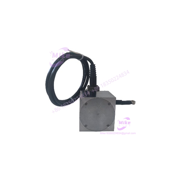
Celesco PT801-0005-611-1111 | 5-Inch Cable-Extension Position Transducer
Dynamic Product Introduction
Field engineers know that measuring linear movement on hydraulic cylinders, heavy press dies, or structural testing rigs requires position feedback hardware that tolerates shaft misalignment without breaking. Rigid rod transducers often bind or bend when structural deflection occurs during heavy cycle loads. The Celesco PT801-0005-611-1111 solves this physical alignment issue by using a stainless steel measuring cable coiled on a threaded drum, providing reliable linear position tracking across a compact 5-inch stroke window.
Built around an IP67 powder-coated aluminum enclosure, the PT801-0005-611-1111 uses a precision hybrid potentiometer to deliver smooth voltage divider feedback across its full measuring range. The internal spool mechanism maintains constant cable tension, eliminating slack and backlash during rapid directional shifts. Whether installed on flight simulators, industrial stamping presses, or automated gate actuators, the PT801-0005-611-1111 provides consistent feedback—though long-term accuracy depends heavily on keeping the measuring cable free from sharp bend angles.
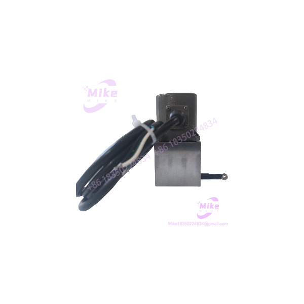
PT801-0005-611-1111
Key Technical Specifications
- Manufacturer & Series: Celesco / TE Connectivity PT8000 Series
- Full Measuring Range: 0 to 5 inches (0 to 125 mm)
- Output Signal Type: Voltage Divider (Potentiometric) / Hybrid plastic potentiometer
- Accuracy / Linearity: \pm 0.1\% full scale repeatability
- Enclosure Rating: NEMA 4 / IP67 powder-coated aluminum housing
- Measuring Cable Material: Stainless steel aircraft cable
- Maximum Cable Acceleration: Up to 10g continuous spring tension tracking
- Cable Tension: High-tension internal spring assembly
- Operating Temperature Range: -40^\circC to +100^\circC (-40^\circF to +212^\circF)
- Connector / Wiring Interface: Industrial multi-pin connector / sealed terminal connection
- Weight: Approximately 1.4 kg (3.0 lbs)
Global Sourcing & Live-Test SOP (Transparency Core)
Procuring secondary-market linear position sensors requires thorough bench testing to ensure internal potentiometer linearity before mounting units onto automated test rigs. Every Celesco PT801-0005-611-1111 passing through our inventory undergoes a strict quality control routine:
- Inbound Verification: Serial numbers and ordering codes on the aluminum body label are verified against factory build sheets. We inspect the housing seals, examine the stainless steel measuring cable for fraying or kinks, and check the spring retraction tension.
- Live Simulation: The PT801-0005-611-1111 is mounted onto a precision linear actuator test bench. A clean 10 VDC excitation voltage is applied across the wiper circuit from a regulated bench power supply.
- Diagnostics: The measuring cable is extended in 0.5-inch increments to its full 5-inch stroke using a digital caliper fixture. Output voltage is measured with a Fluke 87V multimeter to confirm linear voltage scaling holds strictly within the \pm 0.1\% linearity tolerance window.
- Dynamic Tension Check: Fast retraction cycles test spring return speed to confirm zero cable slack and verify smooth internal drum tracking across the entire stroke.
- Final Prep: Terminal connections are cleaned, the measuring cable eyelet is secured with protective tubing, and the PT801-0005-611-1111 is packed in conductive ESD-safe cushioning.
The Field Engineer’s Pitfall Guide
❗ Misaligning the Measuring Cable Exit Angle: Never allow the measuring cable of the PT801-0005-611-1111 to extend at an angle greater than 5^\circ from the centerline of the cable exit orifice. Running the cable at an off-axis angle causes the wire to rub against the internal guide bushing, fraying the stainless strands and introducing friction that ruins measurement accuracy.
❗ Releasing the Measuring Cable Under Full Tension (Free-Wheeling): Never pull the cable out and let go of the eyelet, allowing it to snap back freely into the housing. Free-wheeling causes the internal spool mechanism to over-speed, damaging the internal spring assembly and destroying the precision hybrid potentiometer wiper.
❗ Exceeding Recommended Excitation Voltage Limits: Applying unbuffered or high-voltage power to the potentiometric wiper circuit can burn out the internal hybrid track. In field deployments, connecting the PT801-0005-611-1111 directly to a high-current DC power supply without current-limiting resistors will melt the internal wiper brush.
Intent-Driven FAQ
Q: What do the specific numbers in the PT801-0005-611-1111 part number designate? The part number defines the physical build options: designates the basic heavy-duty string pot model with potentiometric output. -0005 specifies the 5-inch stroke range. The remaining numerical suffixes (-611-1111) define the enclosure material, cable type, spring tension level, electrical interface connector, and mounting bracket options.
Q: Can I connect the PT801-0005-611-1111 directly to a standard PLC analog input card? Yes. Since the PT801-0005-611-1111 operates as a standard voltage divider (potentiometer), you can supply a regulated 5 VDC or 10 VDC excitation voltage across the outer terminals and wire the variable wiper signal into a voltage-capable analog input module.
Q: Is the PT801-0005-611-1111 suitable for outdoor or high-moisture environments? Yes. The PT801-0005-611-1111 features a NEMA 4 / IP67 sealed aluminum enclosure designed to withstand outdoor weather exposure, water spray, and dust intrusion. However, ensure the electrical connector is properly sealed or boot-protected during installation.
Q: What is the main difference between the PT801 potentiometric series and the PT8420 series? The PT801 series provides a raw potentiometric (voltage divider) output that scales proportionally with excitation voltage. The PT8420 series includes built-in signal conditioning electronics that output a standardized 2-wire 4–20 mA current loop.
Q: How can I check if an installed PT801-0005-611-1111 has a worn potentiometer track? Disconnect the electrical plug. Connect an ohmmeter between the wiper terminal and one side of the potentiometer track. Slowly extend the cable by hand—if the resistance reading jumps erratically or drops to open circuit, the internal track or wiper brush has worn out.





