Description
Allen-Bradley 354792-A01 Board | Control System Hardware Spec Sheet
Architect’s Product Breakdown
The Allen-Bradley 354792-A01 serves as a critical internal subassembly card utilized across legacy and active industrial automation infrastructure. Designed to interface seamlessly within rack or chassis backplane environments, this component handles specialized control routing or power conditioning duties depending on the parent drive or controller architecture it supports. Its primary objective is to maintain reliable signal transmission and process stability under heavy electrical loads and fluctuating industrial operating conditions.
Integration requires careful adherence to manufacturer mounting procedures, proper grounding protocols, and verification of hardware revision matches. Mismatching subassembly revisions during maintenance cycles can trigger backplane communication faults or internal power rails dropping out. Technicians must inspect slot alignment carefully and ensure static-safe handling practices are strictly maintained during installation to prevent sensitive surface-mount trace damage.
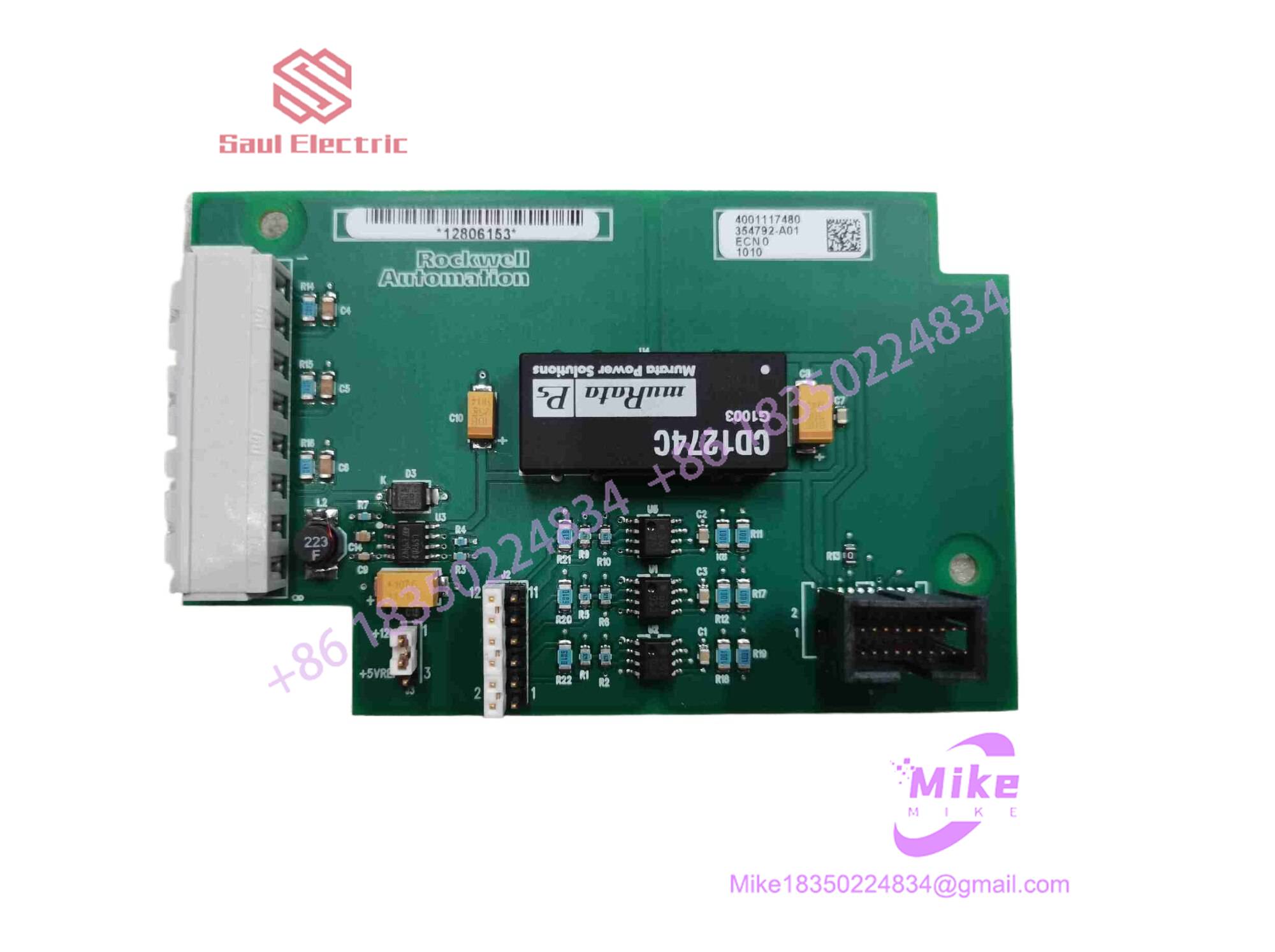
354792-A01
Key Technical Specifications
| Parameter | Specification Data |
| Module Type | System Subassembly / Interface Card |
| Hardware Revision | A01 |
| Enclosure Type | Open-style board level module for rack mounting |
| Operating Temperature | 0^\circC to +50^\circC |
| Storage Temperature | -40^\circC to +85^\circC |
| Relative Humidity | 5% to 95% non-condensing |
| Mounting Style | Chassis slot / Backplane plug-in |
| Compliance | Industrial CE, UL framework standards |
Field Engineer’s Pitfall Guide
- Electrostatic Discharge Vulnerability: Handling this bare board module without a grounded wrist strap or on an unmitigated workbench can instantly fry sensitive CMOS logic gates. Always utilize proper ESD containment gear.
- Revision Mismatch Faults: Swapping an -A01 revision card into a system requiring a later firmware-matched hardware iteration can cause persistent rack-level communication timeouts. Always cross-reference the bill of materials.
- Backplane Pin Contamination: I have diagnosed numerous phantom hardware faults caused simply by microscopic oxidation or dust buildup on the backplane edge connectors. Always clean card-edge fingers with approved contact cleaner before seating.
QA & Testing SOP (Transparency)
- Visual & Origin Inspection: Verification of OEM manufacturing labels, revision stamp integrity (-A01), and trace inspection for physical anomalies.
- Bench Test Environment: Insertion into a dedicated emulation test rack to monitor current draw and logic handshake response.
- Diagnostic Handshake: Verification of internal power rail stability, watchdog timer activity, and communication port throughput.
- Packaging: Antistatic metallic shielding bag packaged inside high-density molded foam containers to eliminate transit vibration damage.
Technical FAQ
- Is this module hot-swappable during active machine operation? No, standard practice requires powering down the parent chassis or rack assembly before inserting or removing this subassembly module.
- What does the “-A01” suffix designate? It denotes the initial hardware production revision tier of the component architecture.
- Does the module store configuration parameters locally? No, operational programming and configuration parameters are handled by the main system controller or non-volatile memory modules on the parent rack.
- What causes diagnostic fault LEDs to trigger upon installation? Fault flags usually indicate an unseated backplane connector, an incorrect hardware revision match, or an upstream power supply voltage sag.