Description
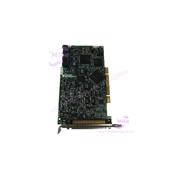
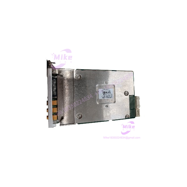
NI PXIe-6548 | 32-Channel High-Speed Digital I/O PXI Express Card
Dynamic Product Introduction
Test engineers running automated semiconductor validation rigs or complex avionics bus emulation stands know how fragile high-speed digital timing margins can be. When a primary digital pattern generator drops channels or suffers clock jitter, finding a direct hardware replacement that restores precise digital stimulus without requiring a rewrite of legacy pattern files is a critical priority.
The NI PXIe-6548 packs 32 bidirectional digital channels into a single PXI Express slot, operating at generation and acquisition rates up to 200 MHz. Engineered for demanding logic validation, the module features software-programmable logic levels from 1.2 V to 3.3 V with sub-nanosecond delay adjustment per channel. Paired with onboard pattern memory, hardware-timed edge generation, and high-speed PXI Express data streaming, the PXIe-6548 delivers the timing resolution and channel density required for memory bus testing, custom protocol emulation, and mixed-signal IC verification.

PXIE-6548
Key Technical Specifications
- Digital Channels: 32 bidirectional channels + 2 clock/control lines
- Maximum Data Rate: Up to 200 MHz (200 Mbit/s per channel)
- Supported Voltage Levels: Programmable 1.2 V, 1.5 V, 1.8 V, 2.5 V, and 3.3 V logic families
- Data Transfer Modes: Single Data Rate (SDR) and Double Data Rate (DDR)
- Timing Adjustment: Per-channel sub-nanosecond programmable delay engine (picosecond-level resolution)
- Onboard Memory: Options for deep onboard pattern memory per channel
- Data States: Drive high, drive low, tristate, compare high, compare low, compare keep
- Hardware Pattern Matching: Real-time hardware comparison and response engines
- Bus Interface: PXI Express Gen 1 x1 peripheral slot interface
- Connector Type: Front panel 68-pin VHDCI connector
Global Sourcing & Live-Test SOP (Transparency Core)
Sourcing replacement digital pattern generator cards requires thorough hardware pattern generation and timing skew verification to ensure stable signal generation across high-speed test harnesses.
Inbound Verification & Traceability
- Paperwork Audit: Validation of physical serial numbers against OEM manufacturing logs to confirm hardware build revision and factory calibration history.
- Physical Inspection: Comprehensive check of the 68-pin VHDCI connector, backplane PCIe edge contacts, shield grounding integrity, and thermal condition of onboard driver ICs.
Live Rack Simulation & Diagnostics
- PXIe Backplane Verification: Module is installed into an active PXI Express test chassis to verify PCIe device enumeration, DMA pattern streaming, and NI-HSDIO driver handshake.
- Full-Speed Pattern Run: Connected to a high-bandwidth digital analyzer to generate and acquire 200 MHz PRBS (pseudo-random binary sequence) test vectors across all 32 channels simultaneously.
- Timing Delay & Skew Calibration Check: Testing per-channel delay engines using high-speed sampling oscilloscopes to verify sub-nanosecond edge placement and channel-to-channel phase alignment.
- 24-Hour Stress Run: Module undergoes a continuous 24-hour thermal chamber burn-in running maximum pattern generation workloads to ensure thermal stability and zero pattern drops.
Final Prep
- EEPROM Verification: Confirming onboard factory calibration constants and non-volatile EEPROM data integrity.
- ESD Safe Packaging: Sealed in anti-static shielding bags with desiccant packs before double-boxed air shipment.
The Field Engineer’s Pitfall Guide
- ❗ Logic Level & VOH/VOL Over-Voltage: Connecting external digital circuits operating at 5 V TTL directly to the PXIe-6548 when its channel buffers are set to 1.8 V or 2.5 V logic will trigger internal over-voltage protection or permanently destroy input buffers. Always verify target voltage level settings in NI-HSDIO before cabling.
- ❗ Improper Cable Termination on Fast Edges: At 200 MHz, digital signal edges require clean 50 Ω transmission line impedance matching. Using unshielded ribbon cables or improperly terminated breakout boxes will cause signal reflections, ringing, and false logic state comparisons.
- ❗ Clock Phase Skew Across Multi-Card Setups: When syncing multiple PXIe-6548 modules for higher channel count systems, failing to route the 100 MHz PXI Express backplane clock (PXIe_CLK100) or neglect setting NI-TClk synchronization calls will introduce clock drift between digital channels.
Intent-Driven FAQ
Will swapping out a damaged PXIe-6548 require updating my LabVIEW application code?
No. Hardware replacement is completely transparent to your host software as long as the replacement module is installed in the same chassis slot and assigned the same alias within Measurement & Automation Explorer (MAX).
What driver software is required to operate the PXIe-6548?
The PXIe-6548 requires the NI-HSDIO instrument driver package. Ensure your host system is running an NI-HSDIO driver build that explicitly supports PXIe-6548 digital hardware.
What breakout accessories are recommended for the PXIe-6548?
NI recommends pairing the module with a shielded 68-pin VHDCI cable (such as the SHC68-C68-D4) and a matching breakout terminal block (such as the CB-2162) to maintain signal integrity at 200 MHz clock speeds.
Is the PXIe-6548 compatible with standard 32-bit PXI slots?
No. The PXIe-6548 utilizes a PXI Express peripheral connector and requires a PXI Express slot or a hybrid PXIe slot. It cannot be physically installed in legacy 32-bit PXI-only slots.
What warranty coverage comes with replacement modules?
All verified PXIe-6548 modules include a standard 12-month full-replacement warranty covering hardware functionality, channel logic generation, and timing engine performance.
If you need help configuring NI-HSDIO pattern files or verifying cable impedance accessories for your PXIe-6548 setup, let me know your target digital bus requirements and I can guide you through the configuration steps.