Description
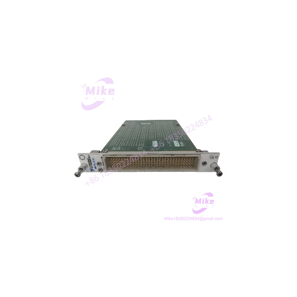
NI PXI-2510 | 68-Channel PXI Fault Insertion Switch Module
Dynamic Product Introduction
Validating automotive Electronic Control Units (ECUs), aerospace controllers, and complex industrial automation systems requires rigorous testing under worst-case electrical fault scenarios. Manually rigging harness breaks or short circuits on test benches introduces safety hazards and inconsistent repeatability. The National Instruments PXI-2510 fault insertion switch module solves this testing challenge by integrating 68 independent SPDT channels directly into a standard 3U PXI slot, allowing automated software injection of open lines, battery shorts, and ground faults.
Designed specifically for Hardware-in-the-Loop (HIL) simulation and stress testing, the PXI-2510 switches up to 100V and 2A per channel while maintaining low path resistance to prevent signal degradation during normal operation. (Honestly, being able to programmatically switch between normal pass-through and fault states via NI-SWITCH driver calls eliminates manual wiring intervention during automated test sequences.) Built with industrial-grade electromechanical relays and integrated self-test diagnostics, the PXI-2510 ensures dependable fault simulation—though long-term relay lifespan depends heavily on managing switching loads within specified voltage and current limits.

PXI-2510
Key Technical Specifications
- Manufacturer & System Platform: National Instruments (NI) / PXI Switching Architecture
- Module Part Number: PXI-2510 / 779313-01
- Total Switching Channels: 68 independent Single-Pole Double-Throw (SPDT) fault insertion channels
- Maximum Switching Voltage: 100 VDC / 100 VAC (rms)
- Maximum Current Capacity: 2 A per channel (carry current), 1 A switching current
- Maximum Switching Power: 60 W (DC), 62.5 VA (AC)
- Relay Type: Electromechanical non-latching armature relays
- Relay Insertion Life: >10^5 operations at full load; >1^7 operations at low signal levels
- Front Panel Connector: High-density 160-pin LFH (Low Force Helix) connector
- Operating Ambient Temperature: 0°C to +55°C (32°F to 131°F) continuous operational range
- Dimensions & Weight: Standard 3U PXI single-slot module, approximately 0.23 kg (0.51 lbs)
Global Sourcing & Live-Test SOP (Transparency Core)
Procuring secondary-market or surplus PXI switching modules demands rigorous electrical and mechanical verification before inserting hardware into automated HIL test racks. Every NI PXI-2510 module entering our inventory undergoes a strict five-stage bench qualification process:
- Inbound Visual & Mechanical Inspection: Serial numbers and PCB revision stamps are cross-referenced against NI manufacturing databases. We inspect the high-density 160-pin LFH front connector for bent or pushed-in pins, check board edge guides, and inspect internal relay arrays for thermal stress.
- Live PXI Rack Simulation: The PXI-2510 module is inserted into an NI PXI-1033 or PXIe-1082 chassis linked to a host development PC running LabVIEW and NI-SWITCH.
- Channel Continuity & Path Resistance Testing: Using a precision DMM fixture mated via a breakout cable, we cycle all 68 SPDT channels through normal pass-through and fault states. Path resistance is measured across every contact to ensure values remain well within factory baseline specifications (<0.5\,\Omega).
- Relay Health & Diagnostics Scan: The NI Switch Health Center utility runs a full diagnostic sweep to count relay closure cycles, check for sticking contacts, and verify coil drive integrity across all 68 nodes.
- Final Prep: Non-volatile status registers are reset, the 160-pin LFH connector pins are cleaned with deoxidizing electronic contact cleaner, and the PXI-2510 is sealed inside heavy-duty anti-static moisture-barrier packaging.
The Field Engineer’s Pitfall Guide
❗ Hot-Switching Inductive Loads Beyond Rated Limits: Never hot-switch inductive loads (such as heavy solenoids, relays, or motor coils) exceeding 1 A or 60 W through the PXI-2510 channels. Hot-switching inductive currents causes severe electrical arcing across the relay contacts, welding the mechanical contacts shut and permanently destroying the channel.
❗ Mating Unsecured or Misaligned 160-Pin LFH Cables: When connecting breakout boxes or custom harness cables to the front-panel 160-pin LFH connector of the PXI-2510, failing to fully tighten the retaining screws can cause micro-vibrations in test cells. This intermittent contact creates erratic open-circuit faults that disrupt automated HIL test scripts.
❗ Exceeding Maximum Common-Mode Voltage to Chassis Ground: Always verify that your signal wires do not exceed the maximum working voltage relative to chassis ground (100 VDC/VAC max). Applying higher voltages across the fault insertion paths will break down internal insulation barriers, causing catastrophic short-circuits to the PXI backplane.
Intent-Driven FAQ
Q: What is the primary difference between a standard PXI matrix module and the PXI-2510 Fault Insertion Switch? Standard matrix modules (like the PXI-2530) are designed to route multiple instruments to multiple DUT points dynamically. The PXI-2510 is specifically engineered for fault insertion, featuring a dedicated SPDT architecture on every channel that lets you instantly break a signal line (open circuit) or shunt it to a fault bus (short circuit to ground/battery).
Q: What cable and terminal block do I need to connect signals to the front of the PXI-2510? Because the PXI-2510 uses a high-density 160-pin LFH connector, you typically use an NI SH160-160-D1 shielded cable connected to a compatible terminal block (such as the NI TB-2640 breakout accessory) to cleanly wire your DUT and fault sources.
Q: Can I monitor the health and usage cycle count of the relays on the PXI-2510? Yes. NI provides the Switch Health Center software tool, which tracks relay closure counts and monitors contact resistance. This allows you to predict relay wear and replace or service the module before an unexpected failure halts your test cell.
Q: Does the PXI-2510 require external power supplies to operate the fault insertion relays? No. The PXI-2510 draws its necessary coil-drive operating power directly from the PXI chassis backplane (+3.3V and +5V power rails). External power supplies are only needed if you are routing custom fault voltage sources (such as battery simulation rails) through the fault bus pins.
Q: Is the PXI-2510 compatible with PXI Express (PXIe) chassis slots? Yes. Like most 3U PXI modules, the PXI-2510 is electrically and mechanically forward-compatible with hybrid PXI Express (PXIe) chassis slots, allowing it to operate seamlessly in modern PXIe test systems.