Description
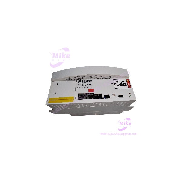
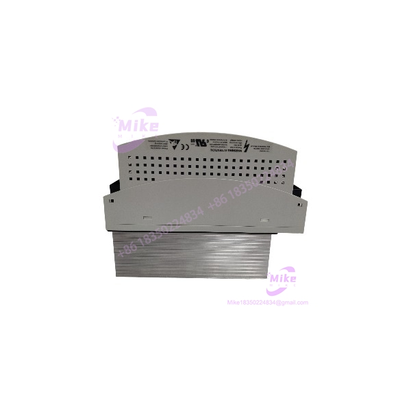
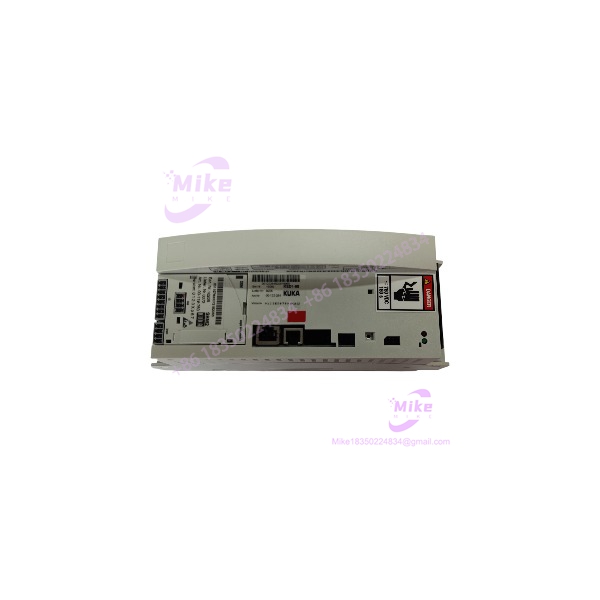
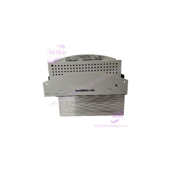
KUKA KSD1-08 | KR C2 Servo Drive Module
Product Introduction
A KUKA robot can lose an axis even when the motor and mechanical transmission are still serviceable. In a KR C2 control cabinet, the KSD1-08 is one of the servo-drive modules responsible for powering and controlling a robot axis. It is not a general-purpose VFD or a standalone motion controller.
The KUKA KSD1-08 is a compact digital servo drive in the KSD1 family. KUKA’s drive documentation describes current/torque control, monitoring of drive functions, and PWM-based power control. Supplier records associate the KSD1-08 with KR C2 control cabinets and list several KUKA article numbers, including 00-122-284 and 00-105-925. These identifiers should not be assumed interchangeable without checking the original drive and system documentation.
For procurement, the practical requirement is to match the installed drive’s complete article number, electrical ratings, feedback arrangement, and controller configuration. A KSD1-08 that appears physically similar may still be unsuitable if its revision or system application differs.
KSD1-08
Key Technical Specifications
- Model: KSD1-08
- Manufacturer: KUKA
- Drive Series:
- Module Type: Digital servo drive
- Frame Size: BG1 / Size 1
- Controller Family: KR C2 / KRC2; confirm exact generation and configuration
- Common Article Number: 00-122-284
- Other Reported Article Number: 00-105-925
- DC-Link Voltage: Up to 565/675 VDC for commonly listed variants; confirm nameplate
- Nominal Output Current: 4.0 A for the commonly listed 00-122-284 version
- Maximum Output Current: 8 A, as reported in family documentation
- Output Type: Three-phase AC
- Output Voltage: Up to 400/480 VAC, depending on variant and system rating
- Output Frequency: Up to 480 Hz, as reported for the common 00-122-284 variant
- Control Method: Field-oriented current/torque control
- Drive Communication: Interbus-based drive-bus interface through the DSE-IBS system
- Power Source: KUKA Power Supply (KPS) DC bus
- Cooling: Forced air / internal heat-sink cooling
- Dimensions: Approximately 88 × 240 × 180 mm (W × H × D), as reported fhe
- Weight: Approximately 1.8 kg
- Protection Rating: IP20 reported by suppliers; verify the exact unit documentation
KUKA’s KSD family documentation lishe at 4 A rated current and 8 A maximum output current, with a 0–770 VDC intermediate-circuit range. Supplier records for individual article numbers provide more specific input/output values. Treat the full article number and applicable KUKA documentation as controlling for replacement decisions.
Global Sourcing & Live-Test SOP
ed should be assessed as a high-voltage servo-drive component. A successful low-level bench check is not equivalent to a verified robot-axis test.
5.1 Inbound Verification
- Photograph the complete nameplate before handling or cleaning.
- Confirm and record the full KUKA article number.
- Check whether the unit is marked 00-122-284, 00-105-925, or another identifier.
- Record serial number, hardware revision, and date-code information.
- Inspect the housing, heat sink, cooling path, and mounting features.
- Examine power and motor connections for damage, discoloration, or contamination.
- Inspect the drive-bus/Interbus interface and feedback connectors.
- Compare the replacement against the original drive’s label and connector layout.
- Request the source controller model and seller test documentation.
5.2 Electrical and Physical Inspection
- Follow the applicable KUKA service and electrical-safety instructions.
- Confirm that the DC bus is fully discharged before handling or disconnecting the drive.
- Do not apply power to unidentified terminals.
- Inspect connectors and accessible components for signs of overheating or prior repair.
- Check cooling components and airflow paths for obstruction.
- Do not perform insulation or high-potential tests unless the applicable KUKA procedure explicitly permits them.
- Record all observed defects and inspection results.
5.3 Controlled Drive Testing
Testing should use an approved KUKA-compatible setup operated by qualified personnel.
- Verify the exact drive article number and applicable test procedure.
- Confirm the compatible power supply and drive-bus arrangement.
- Check the required feedback and motor connections.
- Apply power only under the documented procedure.
- Monitor startup behavior, diagnostic indications, and abnormal current draw.
- Verify communication with the drive-control system.
- Perform output-stage and feedback checks only within the approved test setup.
- Record any drive faults or diagnostic codes.
Do not improvise a high-voltage DC-link test or connect an unknown motor to the drive as a quick screening method.
5.4 System-Level and Extended Testing
Where the appropriate KUKA test environment is available:
- Verify drive recognition by the controller.
- Confirm that the installed axis and motor configuration match the original system.
- Review drive diagnostics before and after testing.
- Conduct controlled functional testing according to the KUKA procedure.
- Monitor thermal behavior, cooling, and fault recurrence during an extended run.
- Document the test duration and actual test scope.
Do not claim a full robot-motion test, 24-hour burn-in, or production-ready status unless that test was actually performed and documented.
5.5 Final Preparation and Packaging
- Preserve the original nameplate and serial number.
- Photograph the unit and all connectors before packing.
- Use ESD-safe packaging and rigid impact protection.
- Protect connectors and heat-sink features against mechanical damage.
- Include available inspection and test reports.
- Clearly identify the unit’s condition as new, used, refurbished, or untested.
- State the exact article number and whether any accessories are included.
Field Engineer’s Pitfall Guide
❗ Match the full article number, nost
units are listed under multiple KUKA article numbers. Supplier records identify 00-122-284 and 00-105-925, with differing electrical data. Confirm the complete number and ratings against the original drive before substitution.
❗ Do not confuhe with a generic VFD
he is part of KUKA’s robot servo-control architecture, with a KPS DC bus and DSE-IBS/Interbus drive interface. Motor feedback, controller configuration, and drive-bus compatibility must be preserved. It is not a generic replacement for a conventional variable-frequency drive.
❗ Treat the DC bus as hazardous even after shutdown
The drive operates within a high-voltage DC-link system. Follow KUKA’s lockout, isolation, and DC-bus discharge procedure before removing or installing the module. Do not assume that a stopped robot or switched-off cabinet means the drive is safe to handle.
Intent-Driven FAQ
What is thKA ?
he is a digital servo-drive module used in KUKA KR C2-era robot-control cabinets. It controls motor current/torque as part of the robot’s multi-axis drive system.
What is the rated current he ?
KUKA family documentation lists 4 A rated current and 8 A maximum output current fhe . Confirm the exact article number and applicable ratings on the installed unit.
What KUKA article numbers are associateth ?
Supplier records asste with article numbers including 00-122-284 and 00-105-925. These should be verified against the original drive label and the target controller documentation before purchase.
Which robot controller ushe ?
Supplier and technical records associahe with KUKA KR C2/KRC2 control cabinets. Confirm the exact controller generation and drive configuration rather than relying he family designation alone.
Can I rep a with aer ?
The model match is a useful starting point, but the complete article number, electrical ratings, feedback arrangement, and controller configuration must also match. Confirm compatibility with KUKA documentation or an authorized service provider before installation.
he hot-swappable?
Do not assume it is. The drive is part of a high-voltage power section. Use the documented KUKA shutdown, isolation, and DC-bus discharge procedure before removing or installing the module.
he obsolete?
Surplus suppliers lihe as discontinued or as a legacy drive, and replacement sourcing is generally through remaining inventory, repair, or exchange channels. Confirm current support and availability with KUKA or the seller.
Bottom Line for Buyers
The is a legacy KR C2 servo-drive module, commonly listed at 4 A rated output current and 8 A maximum current. Its replacement suitability depends on the complete KUKA article number, electrical ratings, drive-bus arrangement, and motor-feedback configuration.
For procurement, request clear nameplate and connector photographs, confirm the full article number, and obtain test documentation tied to the specific unit. A gec “ tested” description is not enough to establish compatibility with a production robot.
For manufacturer information and system documentation, consult the official KUKA website.