

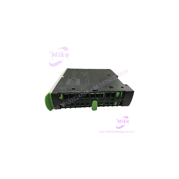
Description
KEBA FM 265/A | PROFIBUS DP Slave Interface Module
Dynamic Product Introduction
The real problem with a failed KEBA FM 265/A is not usually the module itself. It is the fieldbus segment that disappears with it. When a molding machine or other KEBA-controlled production system loses its PROFIBUS interface, drives, remote I/O, sensors, or peripheral devices can stop exchanging process data even though the main CPU is still running.
The KEBA FM 265/A is specifically a PROFIBUS slave communication module, not a general-purpose CPU or analog I/O card. KEBA documents it as part of the KeConnect C2 communication-module family, supporting DPV-1 and both cyclic process-data exchange and acyclic parameter-data access. It can be attached directly to a CPU module or used with KEBA bus couplers.
Its communication range is significant for legacy machinery: the FM 265/A supports transmission rates from 9.6 kbit/s through 12 Mbit/s. At 12 Mbit/s, the documented maximum cable length is 100 m, while slower 9.6 kbit/s operation can reach 1,200 m under the specified conditions. Signal lines are galvanically isolated (important around drives, contactors, and other electrically noisy machinery).
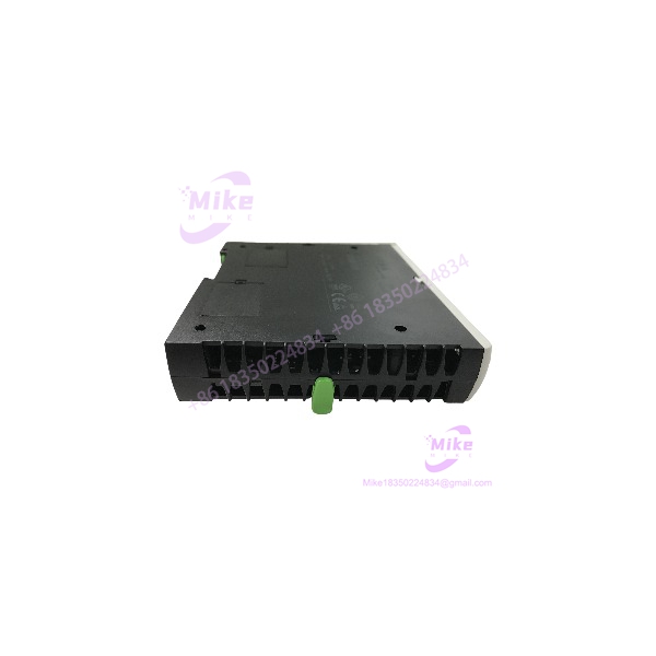
FM 265/A
Key Technical Specifications
- Model: KEBA FM 265/A
- Product family: KeConnect C2
- Application environment: KEBA Kemro K2-200 / compatible KEBA control architecture
- Primary function: PROFIBUS slave interface
- PROFIBUS protocol: DPV-1
- Transmission rate: 9.6 kbit/s to 12 Mbit/s
- Maximum cable length: 100 m at 12 Mbit/s; up to 1,200 m at 9.6 kbit/s
- Signal isolation: Galvanically isolated PROFIBUS signal lines
- K-Bus supply: 24 V and 5 V from K-Bus
- Maximum FM 265/A per CPU: 1 module
- K-Bus 5 V consumption: 1.4 W maximum
- Maximum cycle time: 50 ms
- Status indication: STATUS LED and BUSFAULT LED
- Operating temperature: +5°C to +55°C
- Storage temperature: -40°C to +70°C
- Relative humidity: 10% to 95%, non-condensing
- Dimensions: Approximately 120 mm high × 32.5 mm wide including K-Bus connector × 100 mm mounting depth
- Weight: Approximately 140 g
The FM 265/A should therefore be purchased as a communication-interface replacement, not described as a standalone PLC controller. Some secondary listings incorrectly attribute unrelated analog I/O and Modbus functions to this model; those claims conflict with KEBA’s own documentation, which identifies the FM 265/A specifically as a PROFIBUS slave module.
Global Sourcing & Live-Test SOP
Inbound Verification
For a surplus KEBA FM 265/A, start with the physical identity.
Record:
- Exact FM 265/A marking
- Hardware/type designation
- Serial number
- Electronic identification information
- Connector condition
- K-Bus connector condition
- Front-panel LED condition
- Evidence of corrosion or moisture
- Evidence of previous repair or component replacement
KEBA identifies an electronic parameter chip/nameplate as one of the FM 265/A product features. That provides another useful verification point when checking an incoming module against procurement records.
The current marketplace listing supplied with this request identifies the unit as KEBA FM 265/A FM265A Kemro K2-200 067215 and describes the offered item as used and functional. That listing should be treated as seller inventory information—not as a substitute for an engineering acceptance test.
Live Simulation
A meaningful test requires a compatible KEBA control environment.
The preferred test arrangement should include:
- Compatible KEBA CPU
- K-Bus connection
- FM 265/A
- PROFIBUS master
- Known-good PROFIBUS slave device
- Appropriate PROFIBUS cable and termination
- Engineering/configuration environment
On power-up, check the STATUS and BUSFAULT indicators. Then establish the PROFIBUS connection and verify that the master recognizes the slave.
Do not stop at “the LEDs turn on.” A communication module can pass a power test while failing actual bus communication.
PROFIBUS Diagnostic Test
Run the bus at a representative baud rate and verify:
- Slave address
- DPV-1 communication
- Cyclic process-data exchange
- Acyclic parameter access
- Bus fault behavior
- Communication recovery after cable interruption
- Startup behavior after power cycling
At higher baud rates, inspect cable quality and termination particularly carefully. The FM 265/A supports up to 12 Mbit/s, but the maximum permitted physical segment length decreases substantially as transmission speed increases.
For intermittent faults, I would use a calibrated multimeter for supply verification and a PROFIBUS diagnostic tool/analyzer for bus-level troubleshooting rather than relying exclusively on the PLC diagnostic screen.
Final Prep
Before packaging, record the observed hardware identification and test configuration.
Then:
- Clean connector surfaces without aggressive solvent exposure.
- Protect the K-Bus and PROFIBUS connectors.
- Use ESD-safe packaging.
- Document the tested communication speed.
- Record whether cyclic and acyclic communication were verified.
- Clearly identify the unit as tested used, refurbished, or factory-sealed according to its actual condition.
The Field Engineer’s Pitfall Guide
❗ Do not confuse PROFIBUS slave and master roles. The FM 265/A is documented as a PROFIBUS slave interface. If the existing architecture requires a PROFIBUS master, installing an FM 265/A simply because the connector and housing appear compatible will not solve the problem. I’ve seen replacement projects stall because the fieldbus role was never checked against the original hardware.
❗ Do not ignore the PROFIBUS address and termination. The replacement module has to match the system’s configured slave address, while cable termination and physical-layer conditions must be correct for the selected transmission rate. A bench test at 1.5 Mbit/s tells you very little if the production machine operates at 12 Mbit/s with a marginal cable segment.
❗ Respect the one-module-per-CPU limitation. KEBA’s technical documentation specifies a maximum of one FM 265/A on a CPU module. This is easy to overlook when modifying an older K2-200 architecture. Before adding a replacement, verify the complete K-Bus topology rather than assuming another communication card can simply be stacked alongside it.
Intent-Driven FAQ
What is the KEBA FM 265/A used for?
The KEBA FM 265/A is a PROFIBUS-DP slave interface module used with KEBA control systems. It provides the communication path for cyclic process data and acyclic parameter data between the controller and PROFIBUS devices.
Is FM 265/A a PLC CPU?
No. The FM 265/A is a communication module. It should not be treated as the main KEBA CPU. Its job is to provide the PROFIBUS interface within the control architecture.
Does FM 265/A support PROFIBUS DPV-1?
Yes. KEBA specifies PROFIBUS DPV-1 for the FM 265/A. It supports both cyclic process-data exchange and acyclic parameter-data exchange.
What is the maximum PROFIBUS speed?
The documented range is 9.6 kbit/s through 12 Mbit/s. At 12 Mbit/s, the specified maximum cable length is 100 m; at 9.6 kbit/s, the maximum can reach 1,200 m under the documented conditions.
Can I hot-swap the FM 265/A?
Do not assume it is safe to remove the module while the machine is energized. The available technical documentation establishes the module’s K-Bus architecture but does not justify treating the FM 265/A as a universally hot-swappable device. Follow the machine builder’s shutdown and maintenance procedure before replacement.
What should I check before replacing an FM 265/A?
At minimum, verify the exact model, KEBA CPU family, K-Bus arrangement, PROFIBUS slave address, baud rate, bus termination, cable topology, and application configuration. Also confirm that the replacement has the correct hardware identification. Physical similarity is not enough.
Can FM 265/A communicate with any PROFIBUS master?
The module is designed as a PROFIBUS slave, so compatibility depends on the master configuration, GSD/device configuration, slave address, cyclic data structure, and required DPV-1 functions. The communication speed alone does not establish compatibility.
What warranty should I expect on a used FM 265/A?
That depends on the seller’s written terms. For industrial replacement inventory, confirm the DOA period, functional warranty duration, return conditions, and whether replacement or repair is provided. A statement such as “fully functional” is useful, but it is not equivalent to a documented PROFIBUS communication test.
Procurement Verdict
The KEBA FM 265/A is a specialized PROFIBUS slave interface module for the KeConnect C2 architecture. Its most important replacement characteristics are not generic PLC specifications; they are PROFIBUS role, support, transmission rate, K-Bus compatibility, hardware identification, and correct bus configuration.
For a machine that depends on this module, I would source the FM 265/A against the exact installed part number and then validate the PROFIBUS configuration before commissioning. That approach avoids the classic legacy-automation failure: installing a physically correct module that is electrically alive but logically invisible to the machine.





