


Description
Foxboro FBM214b P0927AH | 8-Channel HART Input Module
Product Introduction
The Foxboro FBM214b P0927AH is designed for plants that need more than a simple analog current measurement. Each of its eight channels can acquire a conventional 4–20 mA signal while also communicating digitally with a HART field device over the same pair of wires.
That distinction changes the commissioning workflow. A standard analog input module primarily delivers a process variable to the DCS; the FBM214b P0927AH also acts as a HART communications host, allowing Foxboro Evo software to exchange HART commands and diagnostic information with supported field instruments. Schneider’s documentation identifies the module as an 8-channel HART communication input module with individually isolated channels.
Each input channel has its own HART FSK modem for bidirectional communication. HART communication uses point-to-point, master/slave, asynchronous, half-duplex signaling at 1200 baud. The module supports HART Version 5, 6, and 7 field devices according to the published functional description.
There is an important limitation: FBM214b does not support HART burst communication mode. Its message-passing capability is intended for universal, common-practice, and device-specific commands initiated through the Foxboro system.
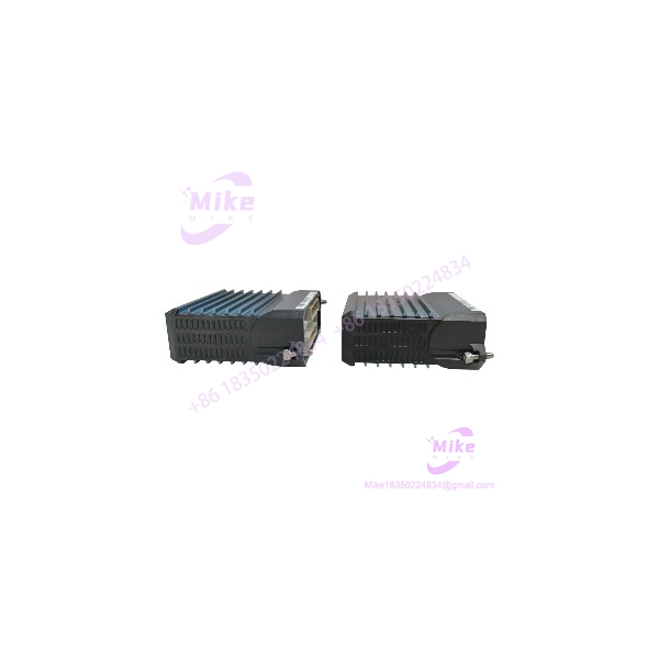
FBM214B P0927AH
Key Technical Specifications
- Model: FBM214b
- Part Number: P0927AH
- Application: HART communication input interface
- Number of channels: 8
- Analog input: 4–20 mA
- HART signal: FSK digital communication superimposed on the 4–20 mA signal
- Channel isolation: Individually galvanically isolated
- HART modem: Dedicated modem for each channel
- HART communication: Point-to-point, master/slave, asynchronous, half-duplex
- HART communication speed: 1200 baud
- Supported HART versions: 5, 6, and 7
- A/D converter: Sigma-Delta
- Analog update: New analog input values available approximately every 100 ms
- Input sense resistance: Approximately 61.5 Ω
- Input resistance: Approximately 282 Ω with externally powered field device
- Input resistance: Approximately 302 Ω with internally powered field device
- Maximum loop-current protection: Current-limited per channel
- Module Fieldbus: Redundant 2 Mbps architecture
- Module mass: Approximately 284 g
- Module dimensions: 102 × 45 × 104 mm
- Height including mounting lugs: 114 mm
- Termination cable length: Up to 30 m
- Baseplate connection: 37-pin D-subminiature
- Termination connection: 25-pin D-subminiature
- Termination cable: Type 1
- Cable material: Polyurethane or LSZH
Schneider Electric’s product specification confirms P0927AH as the FBM214b module part number and specifies the 30 m maximum termination-cable length, 37-pin module-side connection, 25-pin termination-side connection, and 284 g approximate module mass.
HART and Analog Signal Architecture
The FBM214b is intended for mixed HART and conventional analog installations.
A channel can receive a normal 4–20 mA process signal, while a HART-enabled transmitter superimposes its FSK digital communication on the same current loop. The FBM214b separates the analog measurement from the digital HART communication and makes the HART information available to the Foxboro control environment.
This permits a migration strategy in which existing conventional transmitters and newer smart transmitters can coexist on the same I/O architecture.
The module also provides individually isolated field-device power capability. Where an external power source is used, the field-loop resistance and HART signal path need to be checked as part of commissioning. If a common external power source is used across multiple channels, the published installation architecture calls for appropriate measures to prevent HART communication cross-talk.
HART Communication Performance
The FBM214b’s HART function is intended primarily for device configuration, identification, diagnostics, and access to HART process or device data.
The communication method is:
- Point-to-point
- Master/slave
- Asynchronous
- Half-duplex
- 1200 baud
- FSK over the 4–20 mA loop
The module can process HART universal, common-practice, and device-specific commands through the Foxboro HART device-management environment.
Do not specify HART burst mode as a supported feature. The published documentation explicitly distinguishes the message-passing capability from burst communication.
Individually Isolated Channels
Channel isolation is one of the more important specifications when comparing FBM214b with ordinary analog-input modules.
The eight input channels are individually isolated from one another as well as from ground and module logic. This gives the FBM214b a different electrical architecture from modules where multiple analog channels share a common isolation group.
For retrofit work, this can simplify the handling of field instruments with different grounding conditions. It does not, however, remove the requirement to inspect transmitter power supplies, cable shields, grounding points, and termination assemblies.
Isolation should be evaluated as part of the complete loop design rather than treated as a substitute for correct field wiring.
Analog Conversion
The analog portion of the FBM214b uses Sigma-Delta conversion.
The published specification provides approximately 100 ms availability for new analog input values on each channel. This matters when the module is used in a control loop where process-variable filtering, controller scan time, and logic execution are being evaluated together.
A slower configured control response does not necessarily indicate a defective FBM. Before replacing hardware, check the complete signal path:
- Transmitter response
- 4–20 mA loop stability
- FBM conversion
- Configured integration/filtering
- Fieldbus communication
- Controller execution
- HMI update interval
That diagnostic sequence prevents an I/O replacement from being used to solve what is actually a configuration or loop-tuning problem.
Mechanical and Termination Architecture
The FBM214b mounts on a modular baseplate. Schneider documents mounting options including horizontal or vertical DIN rail installation and horizontal 19-inch rack installation with the appropriate mounting hardware. It can also be incorporated into a 100 Series conversion mounting structure.
The termination assembly is separate from the FBM module.
The documented cable architecture uses:
- FBM baseplate: 37-pin D-subminiature
- Termination assembly: 25-pin D-subminiature
- Maximum cable length: 30 m / 98 ft
- Cable type: Type 1
- Cable material: Polyurethane or LSZH
This separation is useful during maintenance because the field termination wiring does not have to be treated as part of the removable electronics module.
Field Replacement Considerations
The FBM214b is designed so that the module can be removed and replaced without removing field-device termination cabling, power cabling, or communications cabling. This is particularly useful when maintaining installed DCS cabinets where disturbing calibrated transmitter loops creates unnecessary process risk.
For a replacement purchase, however, P0927AH alone is not enough information.
Confirm:
- FBM214b model designation
- hardware identifier
- Existing baseplate
- Existing termination assembly
- Termination-cable type and length
- Internal versus external field-device power
- Controller configuration
- HART device-management configuration
- Required environmental rating
- Hardware and firmware revision
A module can be electrically correct yet still create commissioning problems if its termination or system configuration is mismatched.
Global Sourcing & Live-Test SOP
1. Inbound Verification
For a sourced FBM214b :
- Verify the front-panel model marking.
- Confirm against the OEM documentation.
- Record serial number and visible hardware revision.
- Inspect the aluminum enclosure, connector shells, mounting hardware, and baseplate interface.
- Check for oxidation, impact damage, unauthorized PCB repair, flux residue, or connector deformation.
- Trace available OEM paperwork and serial documentation.
- Compare labels and mechanical construction against known Foxboro hardware before accepting questionable surplus stock.
2. Live Simulation
Use a controlled test rack rather than relying solely on visual inspection.
Recommended checks include:
- 4 mA input
- 12 mA input
- 20 mA input
- Multiple channels simultaneously
- HART-enabled transmitter simulation
- Conventional 4–20 mA transmitter simulation
- Internal-loop-power operation
- External-loop-power operation where applicable
- Channel isolation verification
- Module Fieldbus communication
A calibrated current source and suitable HART communicator/simulator should be used for acceptance testing. A handheld multimeter is useful for loop-current verification, but it is not a substitute for a proper HART communication test.





