Description
EMERSON A6120 | AMS 6500 Case Seismic Vibration Monitor, New Surplus
Architect’s Product Breakdown
The Emerson A6120 operates as a critical machinery protection card within the AMS 6500 rack system. Designed specifically to interface with electro-dynamic seismic velocity sensors (or compatible absolute casing vibration detectors), it tracks structural vibration on bearing housings for steam turbines, gas turbines, large compressors, and hydro-turbines. By continuously comparing vibration velocities (typically in mm/sec or inches/sec) against programmed alarm and trip setpoints, the module drives relay actions to safeguard high-value rotating assets from catastrophic mechanical failures.
Deploying or servicing the A6120 card requires adherence to strict rack configuration protocols, parameter scaling, and jumper selections matching the deployed sensor type (such as legacy electro-dynamic types or modern piezoelectric equivalents). Because this card forms part of an API 670 safety protection layer, technicians must verify signal loop integrity, proportional analog outputs (0/4–20 mA), and front-panel buffered outputs during commissioning to ensure reliable trip logic execution.
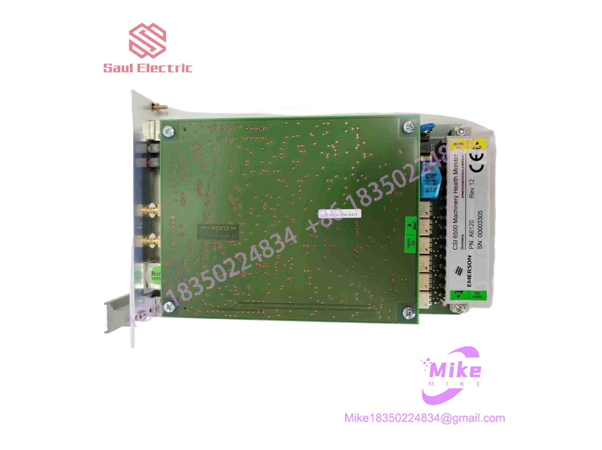
A6120
Key Technical Specifications
| Parameter | Specification |
| Manufacturer | Emerson |
| Part Number | A6120 (AMS 6500 Series) |
| Compatible System | Emerson AMS 6500 Machinery Health Monitor |
| Sensor Compatibility | Electromechanical / Seismic Velocity Sensors (e.g., 9266, 9267, 9268 series) |
| Number of Channels | Dual Channels (Single-slot 3U Eurocard) |
| Measurement Unit | Velocity (mm/s or inches/s) |
| Standard Compliance | API 670 Compliant |
| Outputs | Buffered Proportional Out, 0/4–20 mA, 0–10 V (Front & Rear Panel) |
| Operating Temperature | 0°C to +65°C (32°F to 149°F) |
Field Engineer’s Pitfall Guide
- Electrostatic Discharge (ESD) Hazards: Warning: The fine-pitch traces and integrated circuitry on the A6120 card are vulnerable to static charges. Always use a certified grounded ESD wrist strap and handle the module exclusively by its extraction handles or board edges.
- Hot-Insertion Misalignment Risks: Do not force the module into active rack backplanes. Forcing a card at an angle can bend backplane pins or generate transient power surges that disrupt neighboring protection slots. Ensure proper alignment tracks are followed.
- Ignoring Transducer Scaling & Grounding: Mixing sensor types or leaving shield wires ungrounded introduces severe electrical noise into the seismic velocity loops, risking erratic readings or nuisance machine trips. Verify input scaling parameters match field hardware exactly before clearing the loop for service.
QA & Testing SOP (Transparency)
- Visual & Structural Audit: Incoming cards are examined under magnification for component stress, trace continuity, edge connector wear, and authentic Emerson OEM markings.
- Static Bench & Power Rail Check: Technicians verify internal power isolation, DC rail resistance, and input buffer integrity to guarantee zero internal short circuits.
- Live Rack Simulation Testing: The module is inserted into a certified AMS 6500 test rig and driven with simulated velocity waveforms to validate dual-channel processing accuracy.
- Relay & Trip Logic Verification: Functional checks are performed to ensure 4–20 mA analog outputs, front-panel waveform buffers, and alarm trip relays actuate precisely according to setpoint criteria prior to anti-static sealing.
Technical FAQ
What is the primary difference between the Emerson A6110 and A6120 modules?
While both are 3U plug-in cards for the AMS 6500 system, the A6110 is engineered for shaft relative vibration via eddy current displacement probes, whereas the is designed for casing absolute (seismic) vibration using electro-dynamic velocity sensors mounted directly on bearing housings.
Is the card compatible with modern piezoelectric vibration sensors?
Yes, while historically paired with electromechanical seismic detectors, the module is adaptable to modern installations, though specialized variants like the A6125 are also optimized for specific piezoelectric case measurements.
What causes an input error or fault indication on the front panel?
Common causes include open sensor coils, degraded cabling, ground loops, loss of rack power rail stability, or an unseated card edge connector.
Are component-level field repairs recommended for this module?
No. Because safety protection systems demand absolute reliability under strict API 670 guidelines, component-level micro-soldering is discouraged. Full factory-certified module exchange is standard industrial procedure.