

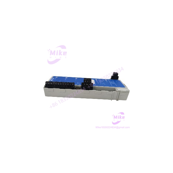
Description
Eaton MTL838C | Modbus RTU Receiver
Architect’s Product Breakdown
The MTL838C occupies the receiving end of the MTL830C temperature multiplexing architecture. It collects measurement data sent by one or two MTL831C analog transmitters, supporting up to 16 sensor channels per transmitter, and makes the resulting values available to a host controller through Modbus RTU. For legacy process plants, this architecture reduces the number of individual field signal cables required between hazardous-area sensors and the control-room cabinet. The receiver is intended for installation in a safe area or a suitably approved Zone 2 location, subject to its certification and installation conditions.
On the control-system side, the MTL838C provides dual RS-485 Modbus interfaces, USB configuration, and two programmable alarm relay outputs. Serial communication settings include baud rates from 300 to 19,200 bps, eight data bits, one stop bit, and selectable odd, even, or no parity. Up to 31 MTL838C receivers can communicate with one Modbus master, subject to the network design and configuration. The receiver’s onboard memory retains configuration parameters during power loss, which simplifies recovery after a supply interruption.
For DCS and PLC integration, the important distinction is that the MTL838C is a Modbus RTU receiver, not an Ethernet Modbus TCP gateway. If the existing system uses Ethernet, verify whether it requires the MTL838C-MBT instead. During replacement, preserve the receiver address, serial communication settings, channel mapping, alarm thresholds, and controller register assignments. A receiver that communicates successfully can still produce incorrect process readings if the host program expects different register addresses or sensor scaling.
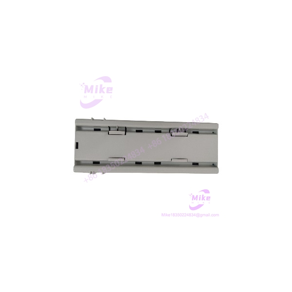
MTL838C
Key Technical Specifications
| Parameter | Specification |
|---|---|
| Manufacturer | Eaton, MTL product line |
| Model number | |
| System family | MTL830C Temperature Multiplexer |
| Equipment type | Analog multiplexer receiver |
| Compatible transmitters | MTL831C |
| Maximum sensor capacity | 32 channels; up to 16 per transmitter |
| Output protocol | Modbus RTU |
| Serial interfaces | Dual RS-485 |
| Baud rate | 300–19,200 bps |
| Serial format | 8 data bits, 1 stop bit, odd/even/none parity |
| USB interface | USB for configuration |
| Alarm outputs | 2 programmable relay contact pairs |
| Supply voltage | 19–30 VDC |
| Maximum current | 300 mA |
| Typical response time | 500 ms, sensor input to Modbus register |
| Operating temperature | −40°C to +70°C |
| Storage temperature | −40°C to +85°C |
| Weight | Approximately 0.19 kg |
| Configuration retention | Onboard memory retains settings during power loss |
| Isolation | 500 V withstand isolation between specified interfaces; relay isolation ratings differ |
| Installation location | Safe area or appropriately approved Zone 2 location |
Specifications are based on Eaton’s MTL830C documentation. Confirm the exact unit revision and applicable certification before installation.
Field Engineer’s Pitfall Guide
Warning 1 — RS-485 settings must match the host.
The supports configurable baud rate and parity. If the replacement has different serial settings from the PLC or DCS configuration, communications may fail even when the wiring is correct. Before removal, record the slave address, baud rate, parity, termination arrangement, and the host’s polling configuration. Also verify the RS-485 wiring polarity and grounding practices specified by the installation manual.
Warning 2 — Do not confuse with -MBT.
The standard provides Modbus RTU over RS-485. The -MBT provides Modbus TCP over Ethernet. They serve related functions but have different host interfaces and network integration requirements. A direct substitution can require changes to PLC communications drivers, network addressing, and control-system configuration. Confirm the exact suffix before ordering.
Warning 3 — Alarm relay behavior needs a controlled test.
The two programmable alarm relay contacts open when their associated alarm condition occurs. A plant that uses these contacts for annunciation, interlocks, or shutdown-related signaling must verify the actual configured alarm conditions and downstream logic before returning the system to service. Do not assume that the replacement contains the same thresholds or alarm assignments as the removed receiver.
A typical legacy-system troubleshooting mistake is replacing the receiver before documenting its configuration. The hardware may be functional, yet the plant can still lose measurement visibility because the serial settings, register mapping, or alarm configuration no longer match. Back up the existing configuration and verify representative sensor readings before releasing the equipment back to operations.
QA & Testing SOP — Transparency
The following is a recommended acceptance procedure. It does not claim that a specific unit has been tested.
1. Visual and origin inspection
- Verify the full model marking, serial information, terminals, and housing.
- Inspect the RS-485 and data-highway terminals, USB connector, and relay contacts for damage or corrosion.
- Record the unit’s condition and any visible evidence of repair or overheating.
2. Power-up and diagnostics
- Apply a controlled 24 VDC supply within the specified 19–30 VDC range.
- Check the power indicator and inspect for abnormal current draw or unexpected heating.
- Confirm that the unit starts without persistent error indications.
3. Communications testing
- Connect a compatible MTL831C transmitter or suitable test setup.
- Verify Modbus RTU communications using the intended baud rate, parity, slave address, and RS-485 wiring.
- Confirm that representative channel values and status information are received correctly.
- Test the second serial interface when required by the application.
4. Alarm and configuration checks
- Verify configuration access through the USB interface and supported MTL83xC configuration software.
- Confirm that configuration parameters persist after a controlled power cycle.
- Test the two programmable alarm outputs against documented settings using a safe, controlled procedure.
- Record actual test results and any functions that were not tested.
5. Packaging and release
- Record the serial number, inspection findings, and test date.
- Use appropriate ESD precautions and protective packaging.
- State the actual condition, warranty terms, and test coverage accurately.
Technical FAQ
Q1: Can the communicate directly with a Siemens, Rockwell, or ABB controller?
Yes, if the controller or an appropriate communications interface supports Modbus RTU over RS-485 and is configured for the receiver’s serial settings and register map. The exact integration depends on the PLC/DCS model, communications hardware, and application configuration.
Q2: Can I replace the with the -MBT without changing the PLC program?
Not necessarily. The standard uses Modbus RTU over RS-485, whereas the -MBT uses Modbus TCP over Ethernet. The PLC communications driver and connection configuration may need modification, even if the intended measurement data is similar.
Q3: Will the retain its configuration after a power failure?
Yes. Its configuration parameters are stored in onboard memory and are designed to remain available after loss of power. Nevertheless, save a separate configuration backup before replacement or maintenance, and verify the settings after restarting the system.
Q4: Can I connect more than one MTL831C transmitter to the receiver?
Yes. One can receive data from one or two compatible MTL831C transmitters, supporting up to 32 sensor channels in total. The transmitter connections, channel assignments, and system configuration must match the intended installation.
Q5: Can the be installed in a hazardous area?
The documented installation locations include the safe area and appropriately approved Zone 2 installations, subject to the specific certification and conditions of use. Do not assume that the receiver is suitable for Zone 0 or Zone 1. The hazardous-area transmitter and associated isolating equipment have separate installation requirements.





