Description
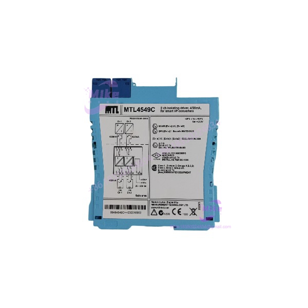
Eaton MTL4549C | 2-Channel Isolating Driver, 4-20mA HART
Architect’s Product Breakdown
The Eaton MTL4549C functions as a two-channel isolating driver built to power and control 4-20mA smart instruments, such as valve positioners and current-to-pressure (I/P) converters, located in hazardous zones. It provides galvanic isolation between the safe-area control system and the hazardous-area field device while supporting bidirectional digital HART communication overlay.
The “C” suffix designation indicates that this model features open-circuit line fault detection (LFD) only, omitting short-circuit detection found on standard variants. When designing loops or replacing legacy hardware, verify that your control system’s digital input card or fault monitoring configuration matches this open-circuit specific behavior to avoid false trip alarms during loop modulation.
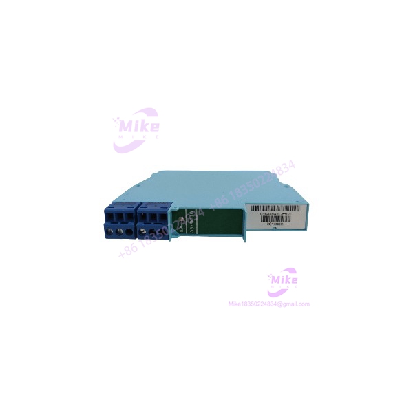
MTL4549C
Key Technical Specifications
| Parameter | Specification |
| Number of Channels | Two channels |
| Input Signal | 4 to 20 mA sourced or sinked from safe area |
| Hazardous Area Output | 4 to 20 mA for smart I/P converters (Zone 0, 1, or 2) |
| HART Communication | Bidirectional (4 kHz to 20 kHz) |
| Line Fault Detection (LFD) | Open-circuit detection only (transistor switch output) |
| Maximum Voltage & Current | 24 V DC nominal bus power |
| Ambient Temperature Range | -20°C to +60°C |
| SIL Capability | SIL 2 / SIL 3 capable per IEC 61508 |
| Mounting | MTL4500 backplane mounting |
Field Engineer’s Pitfall Guide
- WARNING: Misinterpreting LFD Behavior. Do not expect short-circuit alerts from the “C” suffix model. Because the MTL4549C only flags open-circuit faults, a pinched or shorted field cable will not trigger the dedicated LFD transistor output, potentially leaving loop failure undetected by safety controllers.
- WARNING: Current Sink vs. Source Wiring Mismatch. Ensure your control system output card wiring matches the sinking/sourcing requirements specified for the safe-area terminals. Reversing polarity will block current flow and drop the valve positioner to zero.
- WARNING: HART Impedance Drops. Verify that total loop resistance stays within the allowable driving capacity window. Exceeding maximum load resistance will distort the HART communication signal overlay.
QA & Testing SOP
- Visual & Origin Verification: Check the molded plastic housing for damage, verify laser-etched OEM tracking data, and inspect gold backplane edge pins for corrosion.
- Backplane Bench Test: Insert the module onto an active test backplane powered by a regulated 24V DC supply to verify healthy power LED indicators.
- Current Loop Calibration: Inject a 4mA to 20mA signal into the safe-area terminals using a process calibrator and measure the output current on the hazardous side to ensure strict linearity.
- HART and LFD Verification: Test bidirectional communication packet pass-through and introduce an open-circuit condition on the output terminals to validate the LFD transistor status change.
- Packaging: Seal in an anti-static shield bag and pack with dense foam cushioning inside an exterior box.
Technical FAQ
Can I hot-swap this isolating driver while the process loop is live?
Yes. The MTL4500 backplane design allows safe hot-swapping without disconnecting field wiring or powering down the entire rack.
What is the difference between the standard MTL4549 and the MTL4549C?
The standard model includes both open-circuit and short-circuit line fault detection, whereas the MT4549C variant provides open-circuit detection only.
Does this barrier supply power to the field instrument?
Yes. It acts as an isolating driver that energizes the 4-20mA loop for smart positioners and I/P converters located in the hazardous area.
Is configuration software required to install this hardware?
No software is required; the module operates transparently as a galvanic isolator and signal repeater, though field devices connected downstream may require individual HART configuration.