
Description
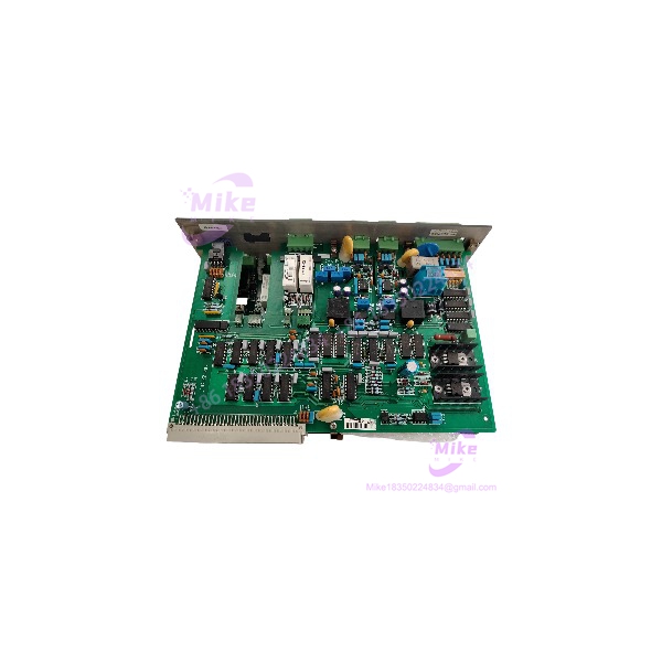
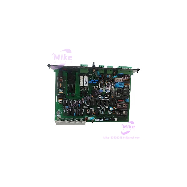
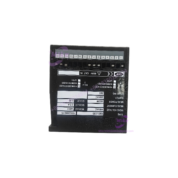
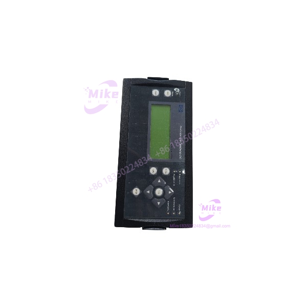
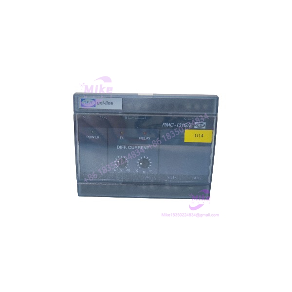
DEIF RMC-131D/2 | Max/Current Protection Relay | In-Stock
Dynamic Product Introduction
Nuisance trips or delayed fault clearing during generator paralleling operations can destroy switchgear components and destabilize emergency power grids. The DEIF RMC-131D/2 provides precise, continuous monitoring of phase currents, ensuring rapid disconnect execution when overcurrent thresholds are breached. Sourcing a fully load-tested DEIF RMC-131D/2 avoids the lengthy lead times of custom retrofit brackets while maintaining exact electrical coordination with existing protection schemes.
Designed to meet strict marine classification standards, the DEIF RMC-131D/2 delivers high mechanical shock resistance and thermal stability within compact generator control panels. Front-panel potentiometers allow field engineers to fine-tune pickup levels and inverse/definite time delays without requiring software programming interfaces. For power engineers managing vessel gensets or standby industrial power stations, integrating this module ensures long-term system availability and full compliance with electrical safety codes.
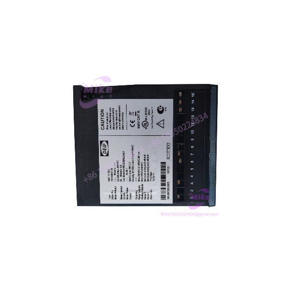
RMC-131D/2
Key Technical Specifications
- Model Identification: DEIF RMC-131D/2
- Monitored Parameter: AC Phase Current (Overcurrent & Short-Circuit)
- Nominal CT Secondary Input: 1 A or 5 A AC (selectable by model variant)
- Auxiliary Supply Voltage: 24 V DC nominal (18 to 30 V DC operational range)
- Trip Output Contacts: 2x Changeover (SPDT) relays, 250 V AC / 8 A resistive load rating
- Overcurrent Setting Range: 50% to 140% of nominal CT rating (I_n)
- Short-Circuit Setting Range: 100% to 400% of nominal CT rating (I_n)
- Time Delay Range: 0.1 s to 30 s adjustable delay curves
- Mounting Type: Standard 35 mm DIN-rail or baseplate mounting
- Operating Temperature: -25°C to +70°C (-13°F to +158°F)
Global Sourcing & Live-Test SOP (Transparency Core)
To ensure fail-safe performance during genuine grid faults, every surplus or reconditioned unit undergoes a thorough 5-stage verification protocol prior to dispatch:
- Inbound Verification: Serial numbers are cross-referenced against DEIF manufacturing indexes, housing latches are inspected, and mechanical calibration potentiometers are verified for smooth resistance curves.
- Live Simulation: The relay is installed on a precision test bench powered at 24 V DC to verify auxiliary power draw and internal watchdog logic startup.
- Current Injection Testing: Using a primary current injection set, step currents from 50% up to 400% of rated I_n are applied while measuring relay trip response times on a high-speed digital timer (Verification: Trip times must match OEM inverse/definite curve characteristics within ±2%).
- Environmental Thermal Burn-In: The module undergoes an 18-hour continuous soak test at 55°C inside an environmental chamber while carrying nominal control current.
- Final Prep: Front dials are calibrated to default baseline positions, terminal screw torque is checked, and the unit is sealed inside anti-static moisture-barrier packaging.
The Field Engineer’s Pitfall Guide
Current Transformer Open-Circuit Safety Warning
Never disconnect the secondary wiring of an active Current Transformer (CT) while the generator is carrying load. Open-circuit CT secondaries generate lethal high-voltage spikes across the terminal block of the DEIF RMC-131D/2.
❗ CT Secondary Rating Mismatch: Installing a 1 A secondary rated DEIF RMC-131D/2 onto a 5 A CT loop causes instant relay tripping at normal load levels, while installing a 5 A relay onto a 1 A loop leaves the generator completely unprotected against thermal overloads.
❗ Auxiliary DC Power Polarity & Ripple: Supplying the DEIF RMC-131D/2 from an unfiltered or poorly grounded DC supply rail can cause erratic timer logic execution. Ensure the 24 V DC auxiliary supply features less than 10% peak-to-peak AC ripple.
❗ Failure to Short CT Terminals During Replacement: Unseating the module without shorting the CT secondary leads at the test block causes arc flash hazards. —In field deployments, I’ve seen an engineer destroy an entire switchgear control section because a live CT secondary lead was left un-shorted during a hasty relay swap.
Intent-Driven FAQ
Can the DEIF RMC-131D/2 be used for both 50 Hz and 60 Hz power systems?
Yes. The frequency response of the internal measuring circuits allows accurate current measurement across both 50 Hz and 60 Hz systems without requiring recalibration.
How do I adjust the short-circuit instantaneous trip setting on the front panel?
Use the dedicated potentiometer marked I>>. Adjust the multiplier scale relative to the nominal CT input rating (I_n) to set the desired instant trip threshold.
Does this protection relay retain its trip status after auxiliary power is lost?
The output relays reset upon loss of auxiliary power unless configured with an external mechanical latching relay block in the switchgear control logic.
What is the recommended diagnostic check if the relay LED fails to illuminate upon powering up?
Measure incoming auxiliary voltage across the 24 V DC terminals using a multimeter (Verification: Voltage must read between 18 V DC and 30 V DC). If voltage is correct, check internal line fuses.
What standard warranty is included with reconditioned or factory-sealed modules?
All reconditioned and factory-sealed units include a comprehensive 1-year replacement warranty covering measurement accuracy, output contact operation, and auxiliary power circuit stability.