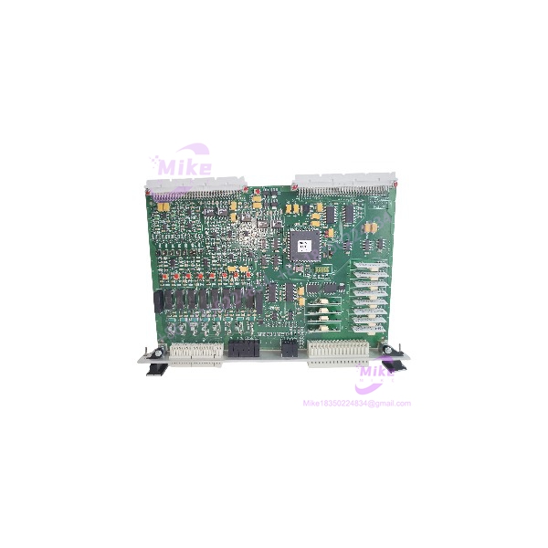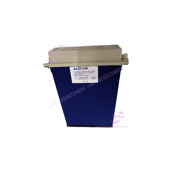
Description
ALSTOM MMLG01 | Relay Protection Test Block
Product Introduction
When a protection engineer needs to inject secondary current or voltage into a relay circuit, the problem is not simply finding a convenient terminal point. The permanent CT, VT, trip, alarm, and auxiliary wiring must remain correctly organized while the test equipment gains controlled access to the required circuits. That is where the ALSTOM MMLG01 earns its place in the protection panel. It functions as a dedicated relay test block, providing a structured interface between permanent field wiring and the associated protection equipment.
The physical architecture is straightforward — and that is a strength in maintenance work. The MMLG01 uses a 14-pole / 28-pin arrangement, with the individual circuits brought to the rear terminal arrangement. It is a passive device, so there is no firmware, processor, communication protocol, or logic program hiding inside the assembly. Its job is physical circuit access and controlled isolation during relay testing (which is exactly what a protection technician generally wants from this type of hardware).
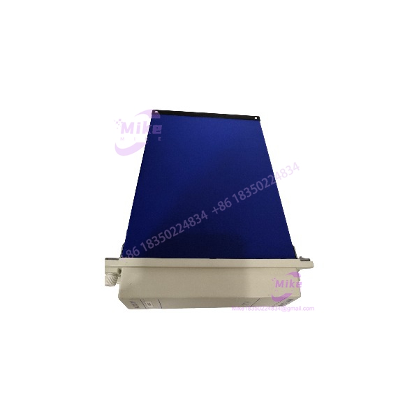
MMLG01
Key Technical Specifications
- Model: ALSTOM MMLG01
- Device Type: Relay protection test block
- Application Family: Midos protection system accessories
- Circuit Arrangement: 14 poles
- Pin Arrangement: 28 pins
- Electrical Architecture: Passive electromechanical interface
- Primary Purpose: Protection relay testing and circuit isolation
- Mounting: Protection-panel / relay-panel installation
- Rear Connection: Dedicated terminal arrangement for permanent wiring
- Test Interface: Designed for use with an appropriate relay test plug
- Typical Circuits: CT, VT, protection, trip, alarm, and auxiliary circuits depending on panel design
- Electronics: No programmable processor or firmware
- Communication: No network communication required
- Maintenance Role: Provides controlled access for secondary injection and protection-system testing
Engineering documentation from an installed 150 kV substation project identifies the ALSTOM MMLG01 as a “RELAY TEST BLOCK” and specifies 14 POLE / 28 PIN.
Application Scenarios & Pain Points
Protection Relay Commissioning
A new relay installation still needs a practical way to perform secondary-injection testing without dismantling the permanent protection wiring.
The ALSTOM MMLG01 provides the fixed interface between the protection circuit and test equipment. A technician can work through the designated test interface rather than repeatedly disturbing individual terminal connections.
That reduces unnecessary wiring manipulation during commissioning.
CT and VT Secondary Circuit Testing
Protection panels frequently contain current-transformer and voltage-transformer secondary circuits alongside trip and auxiliary circuits.
A properly configured installation gives those circuits a defined testing point. The exact circuit assignment depends on the protection-panel schematic — do not assume every 14-pole block is wired identically.
Substation Maintenance
Without a dedicated test block:
Technicians may need to identify individual terminal points, remove links, install temporary connections, and restore everything afterward.
With a correctly installed :
The permanent protection architecture has a designated test interface, making recurring relay-testing procedures more controlled and repeatable.
This is particularly useful in substations where protection testing is performed during scheduled outages.
Transformer Protection Panels
Project documentation shows units installed as relay test blocks within transformer-bay protection systems. Multiple blocks can appear within one protection installation, each associated with specific relay circuits.
Legacy Protection System Preservation
Replacing a failed or damaged test block does not necessarily justify redesigning an entire protection panel.
If the existing wiring, relay arrangement, mounting architecture, and schematic are based around the format, an exact replacement can help preserve the established maintenance procedure.
QA & Live Testing SOP
This is passive protection hardware. That changes the test philosophy.
We do not pretend that powering up an proves anything — there is no PLC processor to boot and no firmware to interrogate.
Instead, inspection focuses on the physical electrical path:
- Model verification: Confirm the complete marking and configuration against the customer’s existing unit.
- Physical inspection: Examine the housing, test interface, terminal area, contact structure, mounting points, and insulation surfaces.
- Contact inspection: Check for bent, damaged, oxidized, contaminated, or mechanically loose contacts.
- Continuity testing: Verify the expected contact paths using a calibrated multimeter or suitable low-voltage continuity instrument.
- Isolation checks: Where appropriate, verify separation between circuits according to the applicable test procedure.
- Mechanical operation: Confirm that the test-interface mechanism operates correctly without binding.
- Terminal verification: Compare the physical terminal arrangement with the customer’s approved protection schematic before installation.
- ESD and packaging control: Protect exposed contacts and connection surfaces during handling and shipment.
The is documented as a passive interface device, so continuity and mechanical/contact verification are more meaningful acceptance checks than a conventional powered functional test.
Field Engineer’s Pitfall Guide
❗ Do Not Assume the 14 Circuits Match Your Existing Wiring
The provides a standardized physical arrangement, but the actual protection circuits connected to each position are determined by the panel engineering.
Compare terminal numbers against the as-built schematic before transferring conductors.
A protection test block can be mechanically correct and still be electrically wrong for the application.
❗ CT Circuits Require Special Attention
Never casually open a live CT secondary circuit while working around a protection test block.
The exact test-plug arrangement and CT shorting provisions must be verified before insertion or removal. A mistake here can create a dangerous secondary overvoltage condition.
Treat the CT circuits differently from ordinary dry-contact wiring.
❗ Do Not Substitute a Random Test Plug
The test block and its associated test plug form a functional pair. Verify the correct plug configuration, circuit assignment, and contact behavior before performing secondary injection.
The is not an electronic relay with configurable firmware; its behavior is determined by its mechanical contact arrangement and the external wiring.
Intent-Driven FAQ
What is the ALSTOM used for?
The is a relay protection test block. It provides a controlled interface for testing protection-relay circuits while maintaining the permanent panel wiring arrangement.
Is the an electronic protection relay?
No. The is a passive test-interface device. It does not execute protection algorithms, contain application firmware, or communicate over an industrial network. Its purpose is controlled electrical circuit access during protection testing.
How many circuits does the provide?
The documented configuration is 14 poles with 28 pins. The individual circuits and their functions depend on how the particular protection panel is wired.
Can I use the for CT and VT protection testing?
It can be incorporated into protection-panel circuits involving CT and VT secondary wiring, but the actual suitability depends on the protection schematic and test configuration. Verify the circuit assignment and required shorting/isolation behavior before connecting test equipment.
Does the require power?
No. The is a passive electromechanical test block and does not require a control-voltage supply or software configuration.
Does the have firmware?
No. There is no programmable firmware to load or match. The important compatibility variables are the physical configuration, contact arrangement, associated test plug, terminal wiring, and protection-panel schematic.
How do I verify an replacement before installation?
Compare the replacement against the existing unit at the model, pole/pin arrangement, physical contact configuration, terminal layout, and mechanical dimensions level. Then verify the intended circuit assignment against the approved protection drawing. Do not install solely because the front label says .
Is the suitable as a direct replacement?
It can be suitable when the existing protection installation was designed around the same configuration. For a field replacement, the safest procedure is to compare the existing hardware and wiring documentation before removing the original unit.
Bottom line: the is specialized protection-panel hardware, not a generic terminal block. Its value comes from providing a controlled, repeatable test interface for relay protection circuits — exactly the kind of small component that becomes very important when a substation maintenance window is already running against the clock.