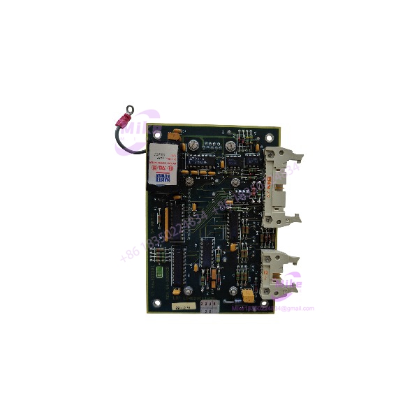
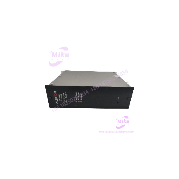
Description
Alstom EPSD-0603 | Flame Indicator Circuit Board
Product Introduction
When a combustion-control cabinet starts generating unexplained flame-status faults, the problem is rarely solved by swapping a generic I/O card. The signal-conditioning and indication hardware has to match the original protection architecture. Alstom EPSD-0603 is identified in current industrial-spares documentation as a dedicated flame-indicator circuit board for combustion and power-generation equipment. Its role is associated with flame-condition sensing, status indication, and feedback into the wider control/protection scheme.
This makes the EPSD-0603 primarily a maintenance and lifecycle-management component rather than a general-purpose PLC module. For legacy Alstom boiler or combustion systems, maintaining the correct board revision can be considerably less disruptive than redesigning an existing flame-monitoring interface. The practical issue is identification: online listings contain conflicting descriptions for this part number, so the PCB label, connector arrangement, hardware revision, and host-system documentation should take precedence over generic catalog descriptions.
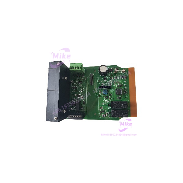
EPSD-0603
Key Technical Specifications
- Manufacturer: Alstom
- Model: EPSD-0603
- Product Category: Flame indicator circuit board
- Primary Function: Flame condition indication and monitoring
- Application Class: Industrial combustion and power-generation control
- Typical Equipment: Boiler, furnace, burner, and thermal-power control systems
- Hardware Format: Electronic PCB / control-board assembly
- System Integration: Installed as part of the host Alstom control architecture
- Signal Role: Flame-status sensing and indication
- Maintenance Role: Replacement spare for legacy installed equipment
- Communication: No standalone external communication protocol should be assumed from the base EPSD-0603 designation
- Electrical Ratings: Not published with sufficient confidence for the base model; verify against the exact board revision and host-system documentation
Important identification note: Some third-party catalogs associate EPSD-0603 with other assemblies, including power-supply and DFI-150-0003-related configurations. Those descriptions conflict with the more consistent identification of the standalone as a flame-indicator PCB. Do not use a generic online voltage, current, temperature, or communication specification as a substitute for the actual nameplate.
Application Scenarios & Pain Points
Boiler combustion monitoring
A failed flame-indication board can produce misleading flame-status information even when the upstream detector is functioning correctly. Replacing the correct board helps isolate the fault at the control-electronics level instead of unnecessarily changing flame sensors or field wiring.
Legacy thermal-power maintenance
The real constraint is often lifecycle support. An older Alstom control cabinet may still perform its process function correctly while individual electronic boards become difficult to source. is therefore relevant as a like-for-like maintenance spare for installed legacy equipment.
Burner and furnace protection
Flame-status information is part of the operating chain between flame detection and combustion control. A questionable indication path can lead to nuisance trips, failed starts, or unnecessary troubleshooting of otherwise healthy field devices.
Emergency replacement stock
For plants operating aging Alstom equipment, holding a verified spare can reduce diagnostic time during an outage. The spare should be matched by exact part number, hardware revision, connector configuration, and application—not simply by physical appearance.
QA & Live Testing SOP
We treat the as a system-specific electronic board, not as a generic PCB.
Step 1 — Identity verification
We photograph and record the complete nameplate, board number, revision marking, connector layout, and visible manufacturing codes. The objective is to prevent a visually similar board from entering the maintenance stock.
Step 2 — PCB inspection
The board is checked for oxidation, cracked solder joints, damaged connectors, burned components, lifted traces, corrosion, and evidence of previous unauthorized repair.
Step 3 — Electrical screening
Before applying power, we check for obvious shorts between relevant supply and return points and inspect protection components. Exact test voltages are determined from the applicable Alstom system documentation rather than guessed from an online listing.
Step 4 — Functional test
Where the correct host test equipment is available, the board is installed into a compatible test configuration and monitored for normal flame-status indication and system feedback.
Step 5 — Final QC
The tested board is protected against ESD and packaged for industrial shipment. Revision information and test results should remain attached to the unit for future maintenance traceability.
Field Engineer’s Pitfall Guide
❗ Do not confuse with DFI-150-0003. Several online catalogs combine these identifiers into a single product description. They should not automatically be treated as interchangeable part numbers.
❗ Do not trust an online voltage specification without checking the actual board. One current listing describes as a DC/DC power-supply module with several possible input ranges, while other sources identify it as a flame-indicator PCB. That contradiction is enough reason to require nameplate-level verification before energization.
❗ Check the host-system revision before installation. A physically compatible PCB can still create commissioning problems if its hardware revision or associated flame-monitoring architecture differs from the installed cabinet.
Intent-Driven FAQ
Q: What is Alstom ?
A: Current industrial-spares documentation identifies the as an Alstom flame indicator circuit board used in combustion and power-generation control applications.
Q: Is a general-purpose PLC I/O module?
A: No. It should not be treated as a conventional PLC digital or analog I/O card. Its documented role is associated with flame indication and monitoring.
Q: Is interchangeable with DFI-150-0003?
A: Do not assume so. Some supplier catalogs combine the two identifiers, but the base and DFI-150-0003 should be verified independently against the equipment documentation and physical labels.
Q: What electrical specifications should I use for ?
A: Use the original equipment documentation or the actual board revision. Published online descriptions conflict substantially, so unsupported voltage, current, and temperature figures should not be used for installation decisions.
Q: What should I verify before ordering an replacement?
A: Confirm the complete part number, board revision, connector arrangement, host cabinet/system, and any additional identifiers printed on the PCB.
Q: Is suitable as a legacy maintenance spare?
A: Yes, provided the replacement is positively matched to the installed Alstom system. Its strongest use case is maintaining an existing combustion-monitoring architecture rather than substituting it into an unrelated control platform.
Q: Why is exact identification important for this part?
A: Because current online sources do not agree on the product classification. For an industrial protection-related board, the physical hardware and original system documentation should override generic marketplace specifications.