


Description
Woodward 8511-144 | Industrial Control Module
Architect’s Product Breakdown
The Woodward 8511-144 operates as an integral component within industrial power management and turbine control architectures. Engineered for high-reliability environments, it handles precise internal logic processing, signal conditioning, and command execution to ensure stable operation of engines, turbines, or associated auxiliary systems. By processing real-time sensor inputs and translating them into accurate actuation commands, it maintains system stability under fluctuating load profiles.
Configuration and parameter adjustments are typically managed via dedicated software toolkits or communication interfaces, allowing technicians to fine-tune control loops without manual component modifications. Proper signal shielding and grounding of input/output wiring harnesses are critical to prevent electromagnetic interference from disrupting control loops in heavy industrial settings.
Deploying a genuine 8511-144 replacement module ensures seamless form-factor, connector, and protocol compatibility, preventing costly integration delays during scheduled maintenance or emergency retrofits.
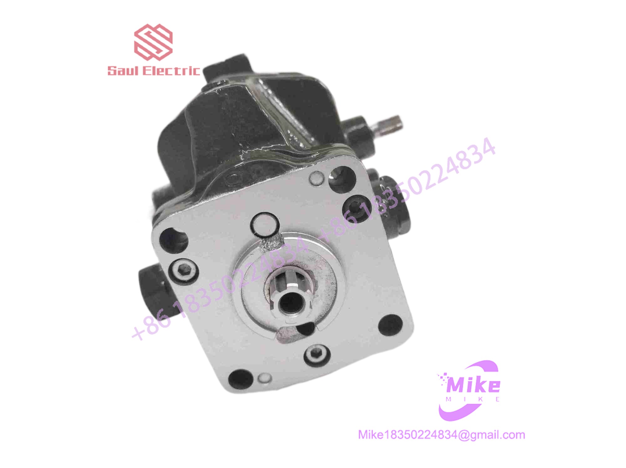
8511-144
Key Technical Specifications
| Parameter | Technical Specification |
| Operating Voltage | Standard industrial DC control power supply |
| Power Consumption | Low-power solid-state architecture |
| Input/Output Channels | Configurable analog/digital control lines |
| Communication Interface | Dedicated service / configuration port |
| Operating Temperature | -20°C to +70°C (-4°F to +158°F) |
| Enclosure Rating | Panel-mount / rack chassis configuration |
| Physical Weight | ~1.0 kg to 2.0 kg (approximate standard format) |
Field Engineer’s Pitfall Guide
- WARNING: Unverified Firmware/Software Revisions. Replacing a module with a mismatched software version without verifying parameter maps can cause unexpected control loop behaviors. Confirm software compatibility prior to commissioning.
- WARNING: Live Backplane Insertion. Never plug or unplug the 8511-144 module into an energized rack or disconnect terminal blocks while system power is active, as voltage transients can damage sensitive logic gates.
- WARNING: Shield Grounding Errors. Failing to properly terminate signal cable shields at a single designated ground point can introduce high-frequency noise into analog sensing circuits, resulting in erratic control responses.
QA & Testing SOP (Transparency)
- Visual & Origin Verification: Inspection of factory identification plates, part number markings, housing integrity, and terminal block pin condition.
- Bench Power & Diagnostic Handshake: Units are mounted on an isolated test bench, powered via a regulated DC source, and verified for clean internal microprocessor initialization and status LED responses.
- Signal Simulation: Technicians inject calibrated input signals to validate channel linearity, control loop responsiveness, and communication port handshakes.
- Final Packaging: Non-volatile memory states are cleared where applicable, and the unit is sealed in an anti-static moisture-barrier bag before being boxed in high-density industrial foam containers.
Technical FAQ
Can I hot-swap this control module while the prime mover is running?
No. Extracting or replacing the 8511-144 while the system is online breaks critical control and safety loops, risking an immediate unit trip or process instability. Perform replacements during scheduled outages.
What software is required to configure or verify a replacement unit?
Depending on the specific system configuration layer, parameter profiles are managed using Woodward’s designated service tool software packages via the appropriate communication interface cable.
Are configuration parameters saved during a total power loss?
Yes. All site-specific calibration profiles and internal parameters are stored in non-volatile flash memory, ensuring data persists safely through complete power interruptions.
What causes a communication timeout or initialization fault on startup?
A startup fault is typically caused by an unseated terminal connector, an incorrect communication baud rate or address setting, or an unstable auxiliary DC power supply rail dropping below operating thresholds.





