


Description
Woodward 8406-121 | EGCP-2 Generator Controller
Product Introduction
When an older generator package refuses to cooperate with a modern controls upgrade, the problem is rarely just the controller itself. Wiring, PT ratios, CT scaling, synchronizing logic, breaker feedback, speed bias, voltage bias, and load-sharing communications all have to agree. The Woodward 8406-121 was built around that complete generator-control problem as part of the EGCP-2 platform, handling engine control, generator synchronization, load control, protection, and sequencing functions in one package.
The defining difference is the sensing range. 8406-121 uses a 50–150 VAC PT input, whereas the closely related 8406-120 is designed for 150–300 VAC PT input. The controller accepts a 9–32 VDC supply, measures generator current through a 0–5 A RMS CT input, and supports 40–70 Hz generator frequency measurement. Its configurable speed-bias output can operate at ±3 VDC, 0.5–4.5 VDC, or 500 Hz PWM, while voltage bias can be configured for ±1, ±3, or ±9 VDC.
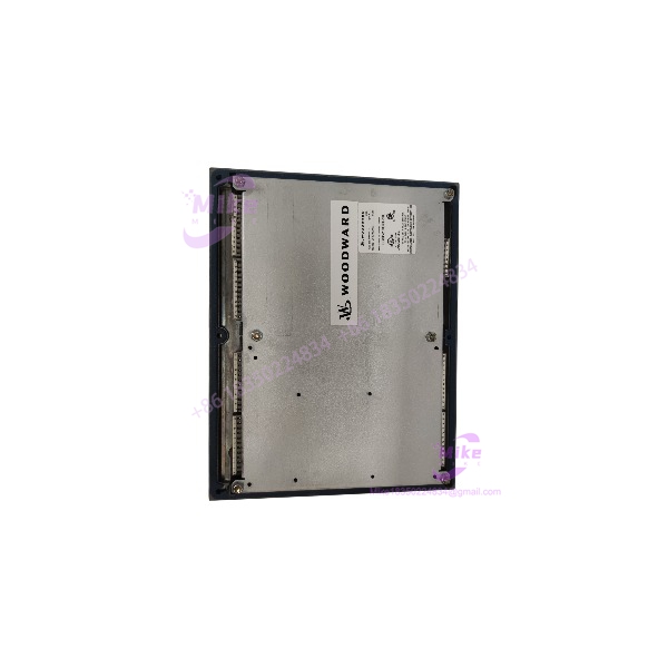
8406-121
Key Technical Specifications
- Manufacturer: Woodward
- Part Number: 8406-121
- Control Platform: EGCP-2
- Application: Engine-generator control and management
- PT Input: 50–150 VAC RMS
- DC Supply: 9–32 VDC
- Nominal Supply: 12 or 24 VDC
- Maximum Power Consumption: 20 W
- CT Input: 0–5 A RMS in the current specification; older documentation lists a maximum 0–6 A RMS range
- Generator Frequency: 40–70 Hz
- Magnetic Pickup Input: Approximately 100–15,000 Hz
- Process Input: 4–20 mA or 1–5 VDC
- Temperature / Pressure Inputs: 0–200 Ω sensors, 4–20 mA transducers, or 0–5 V transducers
- Speed Bias: ±3 VDC, 0.5–4.5 VDC, or 500 Hz PWM
- Voltage Bias: ±1 VDC, ±3 VDC, or ±9 VDC
- Communications: RS-485 and RS-422
- Operating Temperature: -20 to +70°C
- Storage Temperature: -40 to +105°C
- Humidity: Up to 95% non-condensing under specified conditions
- Dimensions: Approximately 358 × 282 × 69 mm
- Installation: Front-panel / sheet-metal housing
- Relay Output Rating: Up to 10 A at 250 VAC resistive or 10 A at 30 VDC resistive
- Display: Dual LCD operator interface with keypad
- Status: Legacy / obsolete EGCP-2 platform
Woodward’s current technical documentation confirms the 8406-121 designation as the 50–150 VAC PT version. That distinction is not cosmetic; using the wrong PT-input variant can produce an incorrect voltage measurement and potentially disrupt synchronization logic.
Application Scenarios & Pain Points
Generator Synchronization
A standby generator does not simply need to start. It needs to reach the correct speed, establish the correct voltage relationship, verify phase conditions, and close the appropriate breaker at the right time.
The 8406-121 provides dedicated speed and voltage bias outputs for synchronization and load-control functions. The speed-bias channel can be configured for ±3 VDC, 0.5–4.5 VDC, or 500 Hz PWM, while the voltage-bias channel supports ±1, ±3, or ±9 VDC.
Utility-Parallel Generator Sets
With the EGCP-2: The controller can coordinate generator synchronization, real kW load control, reactive kVAR control, protection, and automatic sequencing.
Without the correct control architecture: Those functions become distributed across separate equipment, increasing commissioning work and creating more opportunities for mismatched scaling or interlock logic.
The EGCP-2 was specifically designed for small- to medium-sized generator sets and could operate individual units or coordinate multiple generator controls.
Legacy Generator Replacement
This is where exact-part sourcing matters.
A plant may have years of field calibration embedded in an existing configuration. Replacing an 8406-121 with a superficially similar controller can mean rechecking PT ratios, CT scaling, breaker logic, engine parameters, governor bias, AVR bias, and sequencing.
Woodward has published a conversion path from obsolete systems to the easYgen-3200XT, which confirms that the platform is now considered legacy equipment.
Multi-Generator Sequencing
controls can participate in generator sequencing and load-sharing arrangements. Woodward’s technical support documentation also describes EGCP-1/ load-sharing integration with newer easYgen controls through an LSG Loadshare Gateway.
Legacy Communication Networks
The controller provides RS-485 and RS-422 communications, with Woodward identifying the 5417-551 communication cable for configuration and software work.
That matters when restoring an older genset. The communications cable and configuration software are not minor accessories—they can determine whether you can retrieve, inspect, or modify the installed control configuration.
QA & Live Testing SOP
For an controller, powering up the display is only the beginning.
- Origin verification: Confirm the physical label reads Woodward 8406-121 and inspect the serial information, revision marking, housing, display, keypad, and terminal assemblies.
- Variant verification: Confirm the controller is specifically the 50–150 VAC PT version. Do not substitute the 8406-120 simply because the enclosure appears identical.
- Power test: Apply a controlled DC supply within the specified range and verify stable startup, display operation, alarms, and keypad response.
- PT input verification: Test the voltage-sensing circuitry using an appropriate isolated test source rather than applying uncontrolled generator voltage.
- CT input verification: Confirm the current-sensing channel responds correctly under controlled test conditions.
- Discrete I/O: Check input recognition and relay-output operation according to the applicable Woodward test procedure.
- Speed bias: Verify the configured output mode and measure the actual bias signal with a calibrated meter or oscilloscope.
- Voltage bias: Confirm the selected ±1, ±3, or ±9 VDC range and verify output behavior.
- Communications: Test RS-485/RS-422 communication using the correct Woodward interface hardware where available.
- Software revision: Record the application software revision before shipment. Woodward documents multiple upgrade paths, including 8406-121 revisions A through G to revision H using application software 149G_app.hex.
- ESD packaging: Protect the controller from static discharge, impact, moisture, and connector damage during shipment.
For generator-control hardware, a successful power-on test does not prove synchronization performance. Actual commissioning still requires verification of the site-specific PT ratio, CT ratio, breaker logic, governor interface, AVR interface, and protection settings.
Field Engineer’s Pitfall Guide
❗ Do not confuse 8406-121 with 8406-120. The 8406-121 is the 50–150 VAC PT input version. The 8406-120 is the 150–300 VAC PT input version. This is one of the first things to verify before installing a replacement.
❗ Check the software revision before swapping controllers. Woodward documents multiple software revisions and specific upgrade paths. An 8406-121 A/B/C/D/E/F/G unit can have a materially different software history from another unit carrying the same base part number.
❗ Do not inject external power into the discrete inputs. The supplies its own contact-wetting voltage; Woodward’s manual specifically warns that external voltage applied to the discrete-input circuit can permanently damage the control.
❗ Verify the PT ratio before synchronization testing. The calculates and compares voltage measurements using its programmed PT-ratio settings. A correct controller with incorrect PT scaling can still produce incorrect synchronization behavior.
❗ Check the load on the speed and voltage bias outputs. Woodward specifies a minimum input impedance of 1,000 Ω for the bias-output loads. Do not connect these outputs blindly to a low-impedance interface.
Intent-Driven FAQ
What is Woodward 8406-121 used for?
The 8406-121 is a Woodward Engine Generator Control designed to automate and protect diesel- or gas-engine generator sets. Its functions include engine control, synchronization, real and reactive load control, generator protection, engine protection, and sequencing.
What is the difference between Woodward 8406-121 and 8406-120?
The major electrical distinction is the PT sensing range. 8406-121 uses 50–150 VAC PT input, while 8406-120 uses 150–300 VAC PT input. Do not select between them based solely on enclosure dimensions or connector appearance.
What voltage does Woodward 8406-121 require?
The operates from a 9–32 VDC supply, with 12 V and 24 V systems identified as nominal applications. Woodward specifies maximum power consumption of approximately 20 W.
Does 8406-121 support generator synchronization?
Yes. Synchronization is one of the controller’s core functions. The provides dedicated speed and voltage bias outputs that can be configured for different governor and AVR interfaces.
Can I replace an older 8406-121 with a newer 8406-121 revision?
Potentially, but do not treat the revision as irrelevant. Woodward documented software revisions and upgrade paths for the , including conversion of 8406-121 A through G to 8406-121 H. Configuration and calibration data should be preserved and verified before replacement.
Is Woodward 8406-121 obsolete?
Yes. Woodward’s current technical support explicitly describes the as obsolete and provides a conversion path toward the easYgen-3200XT. That makes the 8406-121 particularly relevant as a legacy replacement or maintenance-stock item.
Can I use an 8406-121 for a 150–300 VAC PT system?
No. That is the wrong PT-input version. The 8406-121 is specified for 50–150 VAC PT input; the 150–300 VAC version is the 8406-120. Verify the actual PT secondary voltage and controller part number before installation.
What should I verify before buying a used or surplus 8406-121?
Ask for the actual nameplate, revision marking, front display, rear terminals, and software revision. A clean enclosure alone proves very little. For a legacy generator controller, configuration history and exact electrical variant can matter as much as the base part number.





