


Description
RPSTECH DMP10.24 | Redundant Power Module Core Category
Dynamic Product Introduction
Navigating unexpected voltage drops across continuous process control lines usually forces a scramble for reliable hardware. Deploying the RPSTECH DMP10.24 mitigates that exact vulnerability by injecting fault-tolerant architecture directly into legacy or expanded distribution panels. Unlike standard single-feed blocks that drop logic rails entirely during an upstream failure, this unit utilizes active redundancy switching to maintain uptime without requiring manual intervention.
In field deployments, avoiding micro-interruptions translates directly to zero lost batches and protected field controllers. The DMP10.24 balances a compact footprint with high-density thermal dissipation, bypassing the bulky profile typical of older transformer designs while preserving rigorous signal isolation.
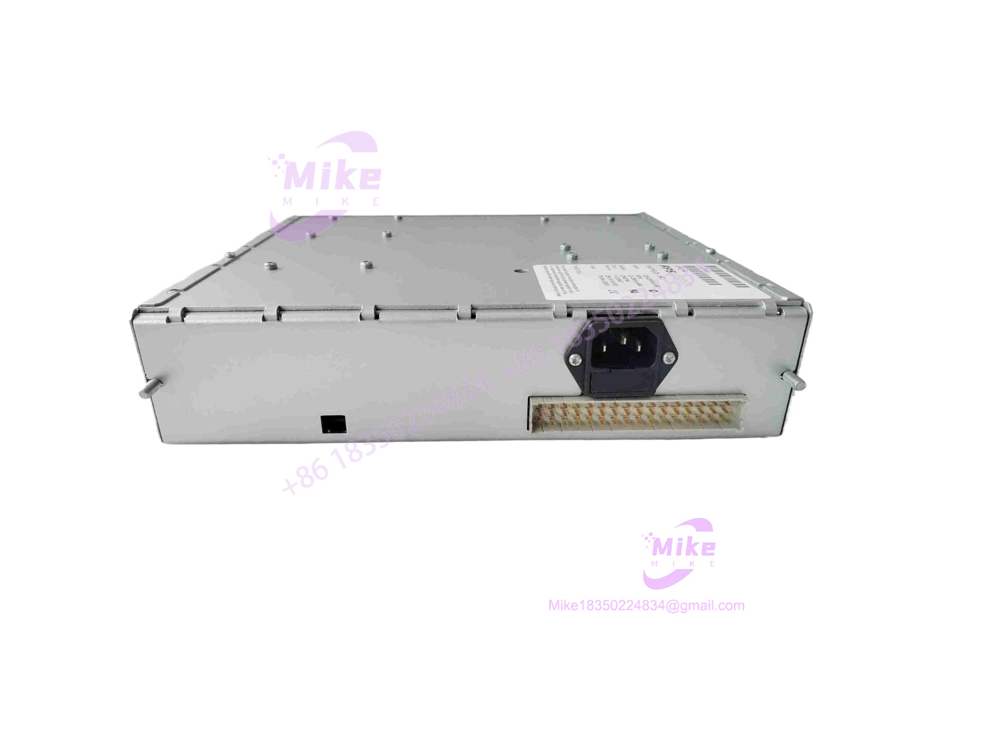
DMP10.24
Key Technical Specifications
| Core Parameter | Technical Specification |
| Input Voltage Range | 21V DC to 28V DC |
| Maximum Input Current | 10A |
| Nominal Output Voltage | 24V DC |
| Maximum Output Current | 10A |
| Mounting Profile | DIN Rail Compatible (Standard 35mm) |
| Module Architecture | Redundant Power / Signal Configuration |
| Operating Temperature | -10°C to +60°C (Standard industrial range) |
| Enclosure Protection | IP20 Open style terminal block layout |
| MTBF Expectation | > 150,000 hours continuous operation |
| Unit Weight | ~1.23 kg |
Global Sourcing & Live-Test SOP (Transparency Core)
Surplus and replacement hardware demand absolute verification before touching an active backplane. Our fulfillment pathway relies on a strict multi-stage protocol:
- Inbound Verification: Every incoming DMP10.24 unit undergoes physical inspection against known OEM anti-counterfeit benchmarks, tracing customs documentation and verifying laser-etched serial numbers against factory registries.
- Live Simulation: Technicians mount the hardware onto a live test rack matching the specified operational voltage to verify baseline thermal stability.
- Diagnostics: Digital multimeters (such as Fluke bench meters) and oscilloscope probes check ripple voltage under load. Full-scale I/O current steps confirm that the redundancy handshakes trigger seamlessly within millisecond thresholds. A 24-hour heat run seals the burn-in phase.
- Final Prep: Technicians record final firmware or hardware revision markers, apply ESD-safe moisture barrier bags, and seal the package for transit.
The Field Engineer’s Pitfall Guide
❗ Overlooking Inrush and Power Draw Limits on Expansion Racks: Slapping a high-draw unit onto an already saturated rail can pull down the main bus. I’ve seen plants lose two days of commissioning because an expansion node exceeded the localized trace capacity of the power distribution tier. Always calculate total loop draw with a safety margin.
❗ DIP Switch and Jumper Blindness: Swapping out an older unit without mapping legacy configuration jumpers often leads to unexpected fault-state latching. Never assume factory defaults match your legacy application.
❗ Terminal Resistor and Grounding Mismatches: Failing to mirror the original shield grounding practices on the DMP10.24 terminal blocks introduces high-frequency ground loops, corrupting sensitive nearby analog signals.
Intent-Driven FAQ
Will swapping the DMP10.24 disrupt my active logic program?
No. Because this hardware operates on the power and signal distribution layer rather than holding non-volatile control logic, physical replacement leaves controller programs untouched—provided proper power-down procedures are followed to prevent arcing.
Is this unit compatible with older revisions of the system architecture?
Yes, backward compatibility is built into the terminal pinouts, but always verify that your input supply rails match the 21–28V DC operational band to prevent low-voltage dropouts.
What kind of warranty accompanies surplus or replacement units?
Verified units typically ship with a standard 365-day operational warranty covering any internal component degradation or manufacturing defects.
How do I handle firmware or hardware revision discrepancies during a swap?
Check the stamped revision label on the side housing against your cabinet documentation. If minor suffix updates exist, cross-reference the manufacturer change notices to ensure backplane protocol compliance.
Can the .24 be hot-swapped safely under load?
While the internal redundancy design protects against single-feed drops, standard industrial safety protocol dictates isolating the primary feed before extraction to protect local terminal pins from pitting.





