

Description
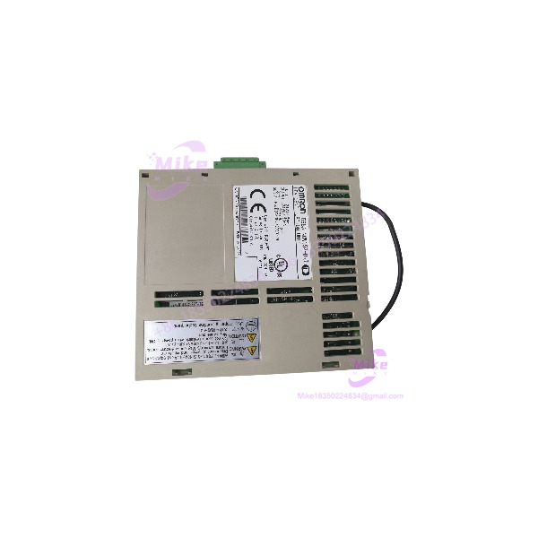
OMRON R88A-NCW152-DRT | DeviceNet Communications Unit Servo Interface
Dynamic Product Introduction
Field engineers managing automated assembly lines or material handling cells know how critical network communication is for multi-axis servo stands. When an active fieldbus option module experiences network communication drops or optical transceiver failure, replacing the interface card without altering the servo drive’s parameter structure or PLC master code becomes an urgent priority.
The OMRON R88A-NCW152-DRT integrates DeviceNet industrial bus connectivity directly into compatible OMRON AC servo amplifiers. Engineered for high-speed motion networking, this option unit allows master controllers (such as OMRON CJ1/CS1 PLCs or third-party DeviceNet scanners) to send target positions, monitor drive status, and read real-time torque/speed feedback over a single 5-wire fieldbus cable. Featuring hardware rotary switches for node addressing, LED network status diagnostics, and optocoupler bus isolation, the R88A-NCW152-DRT provides a reliable communication link for synchronized multi-axis machine control.
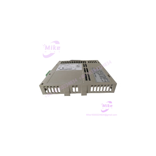
R88A-NCW152-DRT
Key Technical Specifications
- Communication Protocol: DeviceNet fieldbus (Group 2 only / Slave communications)
- Supported Baud Rates: 125 kbps, 250 kbps, and 500 kbps (switch-selectable)
- Node Address Range: 00 to 63 (configured via dual rotary switches)
- Power Supply: Fieldbus power supplied directly through DeviceNet network cable (11 to 25 V DC)
- Bus Isolation: Optical galvanic isolation between DeviceNet network and internal drive electronics
- Diagnostic Indicators: Module Status (MS) and Network Status (NS) dual-color LEDs
- Connection Interface: 5-pin open-style DeviceNet terminal plug (V-, CAN_L, Shield, CAN_H, V+)
- Mounting: Direct option slot insertion on compatible OMRON servo drives
- Operating Temperature: 0 °C to +55 °C industrial range
Global Sourcing & Live-Test SOP (Transparency Core)
Sourcing surplus or replacement industrial fieldbus hardware requires strict electrical verification to guarantee communication stability under full network traffic loading.
Inbound Verification & Traceability
- Paperwork Audit: Verification of serial numbers, model suffixes, and hardware revision codes against OMRON manufacturing logs to confirm hardware authenticity.
- Physical Inspection: Comprehensive examination of edge slot connectors, DeviceNet terminal pins, rotary address switches, and LED indicator light guides.
Live Bench Simulation & Diagnostics
- Drive Attachment & Slot Verification: Module is mounted onto a test OMRON AC servo drive to verify internal bus recognition, parameter initialization, and power rail handshakes.
- DeviceNet Network Communications Test: Connected to a master DeviceNet scanner PLC to verify node address assignment, baud rate synchronization, and I/O assembly data mapping (Explicit/Poll messaging).
- Network Load & Packet Loss Test: Running continuous high-speed motion profiles while streaming real-time torque and position data across a 500 kbps bus to confirm zero dropped packets.
- 24-Hour Thermal Burn-In: Module undergoes a 24-hour stress test inside a thermal chamber under continuous network activity to guarantee bus transceiver stability.
Final Prep
- Switch Reset: Rotary node switches and baud rate dip switches are set to default factory configurations.
- ESD Safe Packaging: Sealed in anti-static shielding bags with desiccant packs before double-boxed shipping.
The Field Engineer’s Pitfall Guide
- ❗ Node Address & Baud Rate Switch Mismatches: Before applying power to the servo drive, ensure that the rotary node address switches (NODE NO.) and baud rate dip switches on the front panel of the R88A-NCW152-DRT match the settings of the replaced unit exactly. Changing switch positions while the drive is powered will not update settings until power is cycled.
- ❗ DeviceNet Cable Power Supply: The R88A-NCW152-DRT requires 24 V DC network power across the V+ and V- pins of the 5-pin DeviceNet connector to power its internal transceivers. If network power drops below 11 V DC, the unit will trigger a Network Error (NS LED red) and drop off the bus.
- ❗ Missing Bus Termination Resistors: High-speed DeviceNet networks running at 500 kbps require 121 Ω termination resistors at each physical end of the main trunk line. Omitting termination resistors will cause signal reflections, high bit-error rates, and intermittent node dropouts.
Intent-Driven FAQ
Will replacing a damaged R88A-NCW152-DRT require re-programming my PLC code?
No. Hardware replacement is transparent to the master PLC as long as the replacement module is set to the same Node Address and Baud Rate as the original unit.
Can the R88A-NCW152-DRT be installed or removed while the servo drive is powered?
No. Always disconnect main power and control power from the host servo drive before installing or removing option modules. Hot-plugging option cards can cause electrical damage to internal drive backplane logic.
What do the MS and NS LED indicators signify during operation?
- MS (Module Status): Green indicates normal internal hardware operation; Red indicates an internal hardware fault.
- NS (Network Status): Solid Green indicates normal online communication; Flashing Green indicates online but not connected; Solid Red indicates a critical communication fault (such as duplicate node ID or bus-off state).
Is a separate external power supply needed for the R88A-NCW152-DRT?
The unit draws its operational communication power directly from the 24 V DC supply carried by the standard 5-wire DeviceNet bus cable. Internal drive logic power is supplied via the drive’s option slot.
What warranty coverage is provided with replacement units?
All verified OMRON R88A-NCW152-DRT option units include a standard 12-month full-replacement warranty covering fieldbus transceiver functionality, switch responsiveness, and internal logic stability.
If you need assistance verifying DeviceNet I/O mapping routines, setting DIP switch configurations, or checking cable termination layout for your R88A-NCW152-DRT setup, let me know your master PLC model and I can assist with the configuration.





